OM-1683-001_w.pdf - 第23页
6 OM-1683 3.2 "Run Mode" T ab Sheet This tab sheet enables the operator to designate the operation mode for each lane. Reference Refer to "4.1 "Run Mode" W indow" in Chapter 1, V olume 2, in…
5
OM-1683
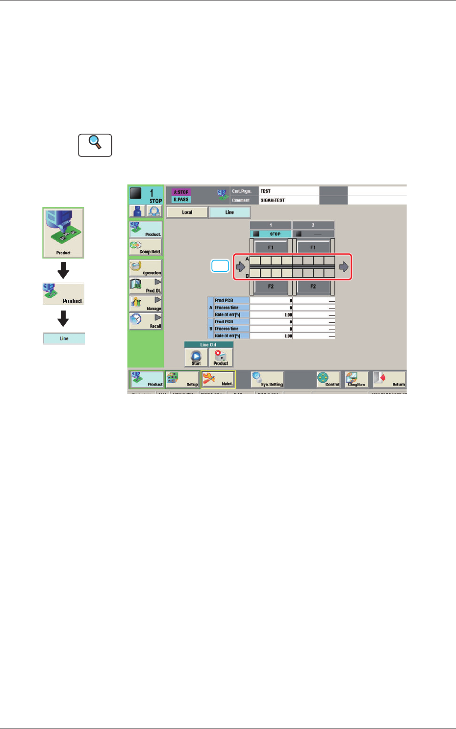
3.1 "Line" Window
This window enables the operator to check the production line operation
status and operate the line.
In this window, the operation status of the SIGMA Series machine (including
the printer) set in the line conguration, and PCB transfer unit graphic image
are displayed.
Reference
Refer to "2.2 "Line" Window" in Chapter 1, Volume 2, in the SIGMA-G5
main machine instruction manual for the information other than for dual
transfer.
[1] [1]
Fig. 5 Line Window
[1] PCB transfer section
In this area, the current PCB transfer status in each lane is displayed.
Green
: PCB present
Gray
: PCB absent
Graphic
Development
1103-001
3.1 "Line" Window
6
OM-1683
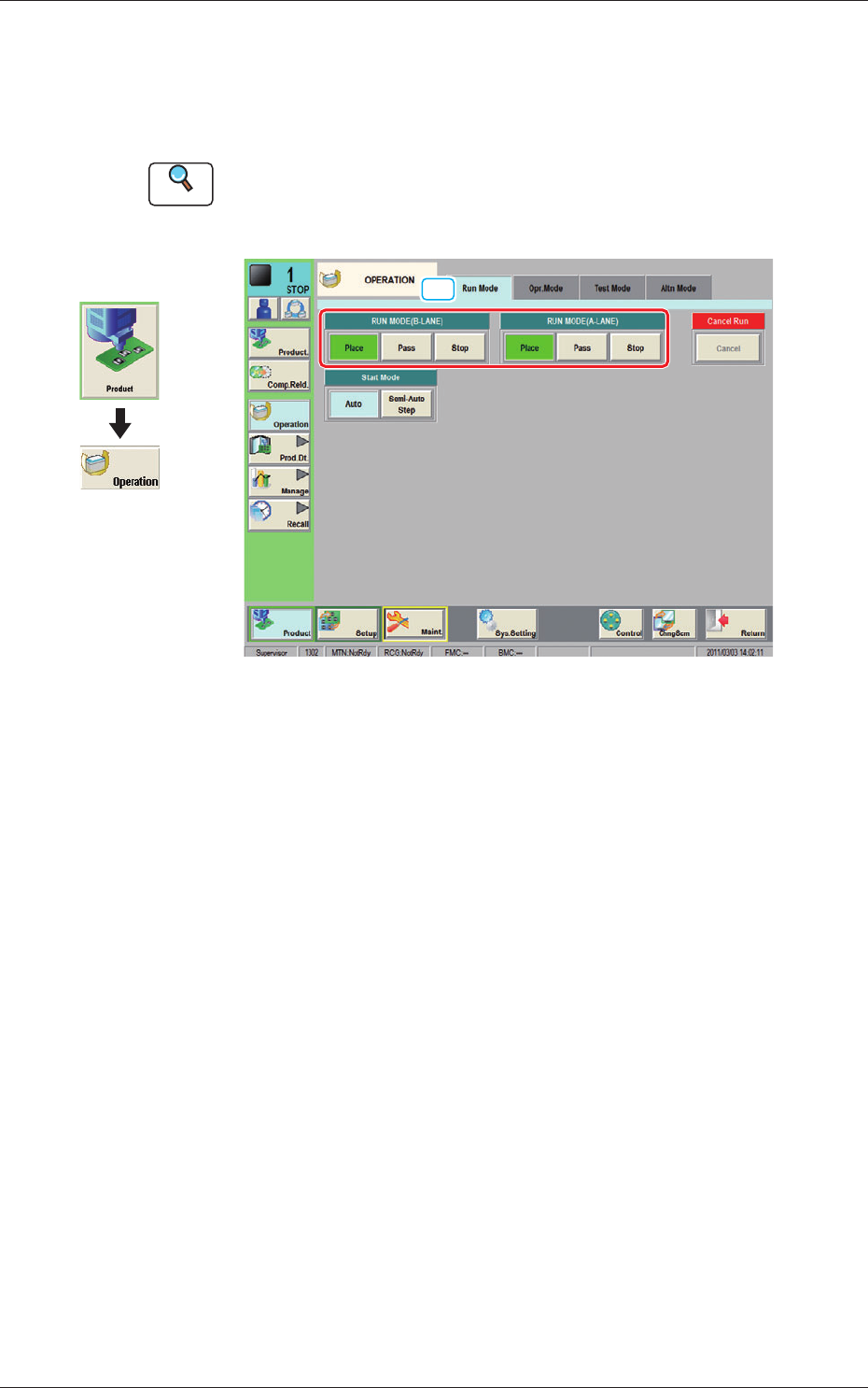
3.2 "Run Mode" Tab Sheet
This tab sheet enables the operator to designate the operation mode for each
lane.
Reference
Refer to "4.1 "Run Mode" Window" in Chapter 1, Volume 2, in the
SIGMA-G5 main machine instruction manual for the information other
than for dual transfer.
[1]
Fig. 6 Run Mode
[1] "Run Mode" Selection Buttons (A or B Lane)
Press either one of the following buttons to select the desired run mode.
[Place] Button
:
Select this button to set the machine in the "PLACE
(Automatic Operation)" mode.
[Pass] Button
: Select this button to set the machine in the "PASS" mode.
In the "Status" display section on the upper area of the "Product." window, the
changed operation mode is displayed.
Graphic
Development
1103-001
3.2 "Run Mode" Tab Sheet
7
OM-1683
1103-001
4. Pattern Program
4. Pattern Program
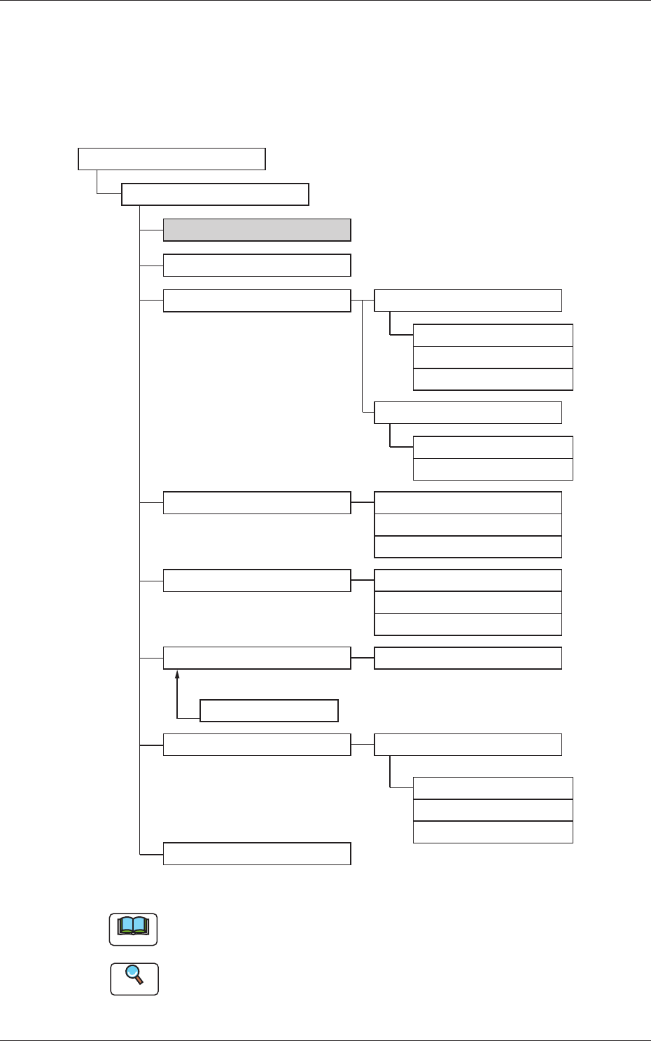
4.1 Composition of Pattern Program
The pattern program for dual transfer consists of the following data items.
Pattern Program
Pattern Program Name
Common SET
PCB
Operation
Control
PL Head/Nozzle
CMPNT PL
Component Library
Component ID
Placement
PCB Recog
Control
PCB locate
Transfer speed
Nozzle Place
Nozzle Stk1
Nozzle Stk2
Function
Mark
Operation
Set-up
Set-up
Support Pin
Block1(2)
Un
Offset
P-data
O-data
HDLG/PL
Fig. 7 Composition of Pattern Program
Note
The item in gray is to be changed for dual transfer.
Reference
Refer to "Pattern Program" in Chapter 2, Volume 2, in the SIGMA-G5
main machine instruction manual for the information other than for dual
transfer.