OM-1683-001_w.pdf - 第27页
10 OM-1683 5. "PP CHANGE" Window This window enables the operator to change the pattern program. Reference Refer to "3. "PP CHANGE" W indow" in Chapter 6, V olume 2, in the SIGMA-G5 main mac…

9
OM-1683
1103-001
4.2 Pattern Program Description
Transfer mode
The transfer mode is set in this selection box.
Dual transfer
When selected, the production is performed using the lanes A and B.
Single transfer
When selected, the production is performed using the lane B.
Note
This function is used when the Y (vertical) in the PCB size is 250 mm
or more.
Used Lane
The lane(s) to be used in the automatic operation is set in this selection box.
A Lane
:
When selected, the automatic operation is performed only in
the lane A.
B Lane
:
When selected, the automatic operation is performed only in
the lane B.
A/B Lanes
:
When selected, the automatic operation is performed both in
the lanes A and B.
P
attern Program Name for Lane A, Pattern Program Name for Lane B,
Bar code
The pattern program name for each lane is set in this group box.
Max. 32 characters can be used to set.
Available characters are half-width alphabetical / numerical characters and
symbols.
10
OM-1683
5. "PP CHANGE" Window
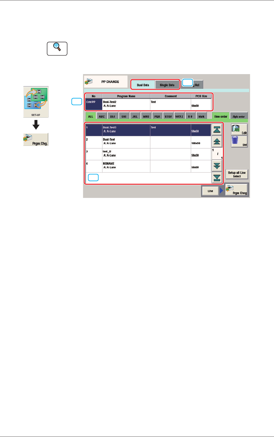
This window enables the operator to change the pattern program.
Reference
Refer to "3. "PP CHANGE" Window" in Chapter 6, Volume 2, in the
SIGMA-G5 main machine instruction manual for the information other
than for dual transfer.
[2]
[1]
[3]
Fig. 9 PP CHANGE
[1] Dual Data, Single Data
Dual Data
When selected, the pattern programs for dual transfer are displayed in the
"
[3] Patter Program List
"
area.
Single Data
When selected, the pattern programs for single transfer are displayed in the
"
[3] Pattern Program List
"
area.
[2] Pattern Program Select tabs
The data items displayed in "[3] Pattern Program List" are divided into the
tab sheet items and displayed.
[3] Pattern Program List
The registered pattern programs are displayed as a list.
When the pattern program has been selected in the dual transfer data, the
program name for each of the Lane A and Lane B, comment and PCB size
are displayed in this area.
Graphic
Development
1103-001
5. "PP CHANGE" Window
11
OM-1683
6. "SPRT-PINS" Window
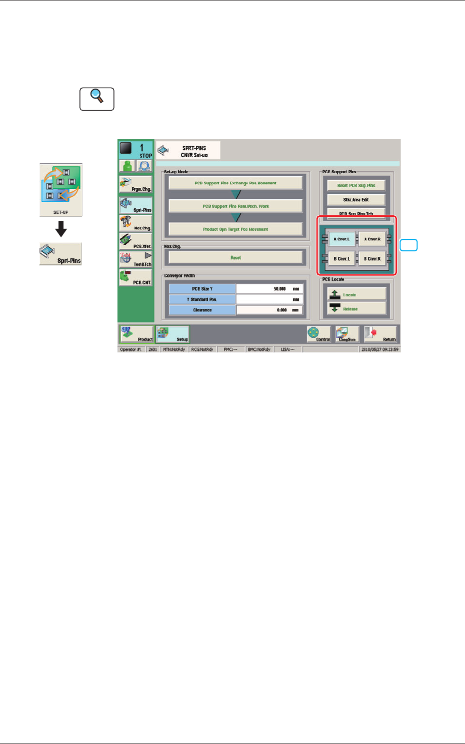
This window is used when the support pin change work for each conveyor is
to be performed.
Reference
Refer to "4. "SPRT-PINS" Window" in Chapter 6, Volume 2, in the
SIGMA-G5 main machine instruction manual for the information other
than for dual transfer.
[1]
--
Fig. 10 SPRT-PINS
[1] PCB Locate Section Select Button
Using these buttons, the PCB positioning section is selected on the side of
set-up operation for each conveyor.
[A Cnvr. L] Button
:
When selected, the PCB positioning section L on the
side of the lane A is selected.
[B Cnvr. L] Button
:
When selected, the PCB positioning section L on the
side of the lane B is selected.
[A Cnvr. R] Button
:
When selected, the PCB positioning section R on the
side of the lane A is selected.
[B Cnvr. R] Button
:
When selected, the PCB positioning section R on the
side of the lane B is selected.
Graphic
Development
1103-001
6. "SPRT-PINS" Window