OM-1683-001_w.pdf - 第28页
1 1 OM-1683 6. "SPRT -PINS" Window This window is used when the support pin change work for each conveyor is to be performed. Reference Refer to "4. "SPR T -PINS" W indow" in Chapter 6, V ol…
10
OM-1683
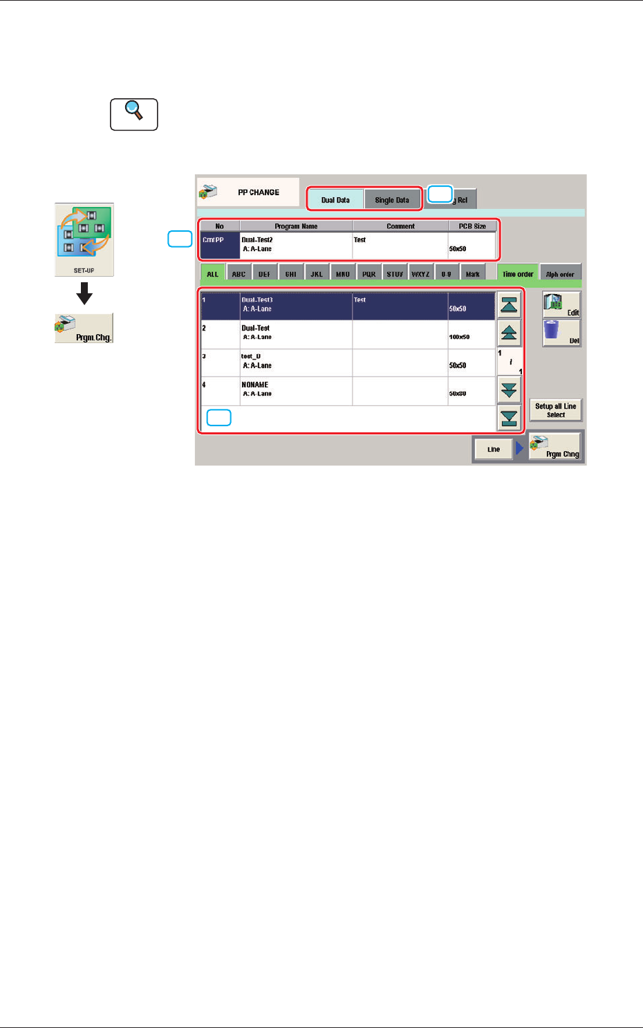
5. "PP CHANGE" Window
This window enables the operator to change the pattern program.
Reference
Refer to "3. "PP CHANGE" Window" in Chapter 6, Volume 2, in the
SIGMA-G5 main machine instruction manual for the information other
than for dual transfer.
[2]
[1]
[3]
Fig. 9 PP CHANGE
[1] Dual Data, Single Data
Dual Data
When selected, the pattern programs for dual transfer are displayed in the
"
[3] Patter Program List
"
area.
Single Data
When selected, the pattern programs for single transfer are displayed in the
"
[3] Pattern Program List
"
area.
[2] Pattern Program Select tabs
The data items displayed in "[3] Pattern Program List" are divided into the
tab sheet items and displayed.
[3] Pattern Program List
The registered pattern programs are displayed as a list.
When the pattern program has been selected in the dual transfer data, the
program name for each of the Lane A and Lane B, comment and PCB size
are displayed in this area.
Graphic
Development
1103-001
5. "PP CHANGE" Window
11
OM-1683
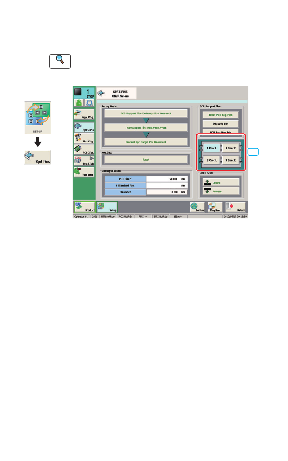
6. "SPRT-PINS" Window
This window is used when the support pin change work for each conveyor is
to be performed.
Reference
Refer to "4. "SPRT-PINS" Window" in Chapter 6, Volume 2, in the
SIGMA-G5 main machine instruction manual for the information other
than for dual transfer.
[1]
--
Fig. 10 SPRT-PINS
[1] PCB Locate Section Select Button
Using these buttons, the PCB positioning section is selected on the side of
set-up operation for each conveyor.
[A Cnvr. L] Button
:
When selected, the PCB positioning section L on the
side of the lane A is selected.
[B Cnvr. L] Button
:
When selected, the PCB positioning section L on the
side of the lane B is selected.
[A Cnvr. R] Button
:
When selected, the PCB positioning section R on the
side of the lane A is selected.
[B Cnvr. R] Button
:
When selected, the PCB positioning section R on the
side of the lane B is selected.
Graphic
Development
1103-001
6. "SPRT-PINS" Window
12
OM-1683
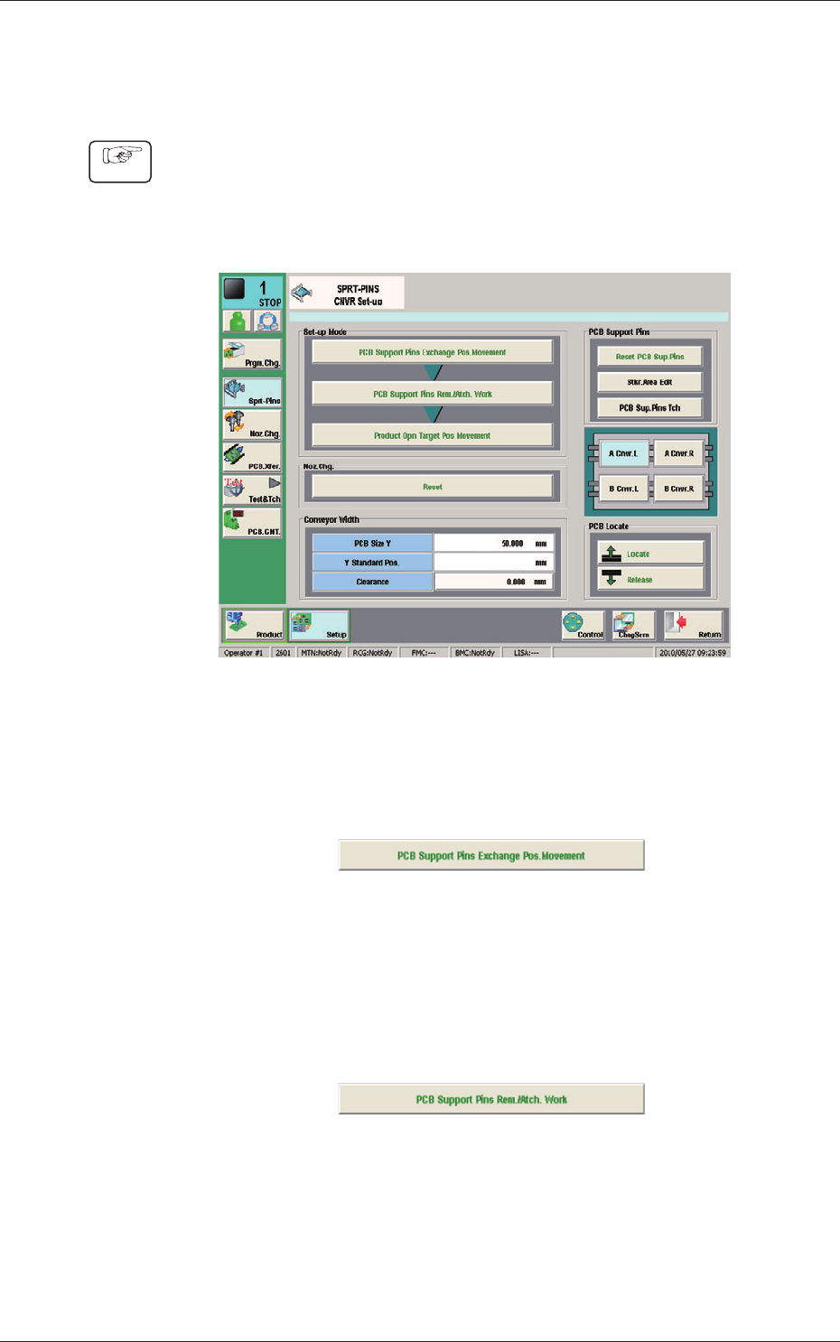
6.1 Collection of PCB Support Pins and Setup Operation of
Conveyor Width
(1) Display the "SPRT-PINS CNVR Set-up" window using the following icon
procedure.
(2) Select the conveyor in the lane where the operation is
performed.
--
Fig. 11
(3) Press the [PCB Support Pins Exchange Pos. Movement] button.
After that, press the [START] button on the operation panel in 10 sec.
(The machine retracts the head and maximizes the conveyor width.)
Fig. 12
(4) Press the [PCB Support Pins Rem./Atch. Work] button and within 10
seconds, press the [START] button on the operation panel.
(The PCB support pins are arranged onto the positions specied in the
pattern program).
Fig. 13
(5) Press the [Product Opn Target Pos.Movement] switch and within 10 seconds,
press the [START] button on the operation panel.
The support pins are moved based on the pattern program where the
conveyor width has been selected.
Procedure
1103-001
6.1 Collection of PCB Support Pins and Setup Operation of Conveyor Width