OM-1683-001_w.pdf - 第39页
22 OM-1683 1 103-001 12. Machine System 12. Machine System Fig. 22 Offset Data Notice Do not change the parameters unless nece ssary . These parameters are factory-adjusted upon shipment of the machine. Graphic Developme…
21
OM-1683
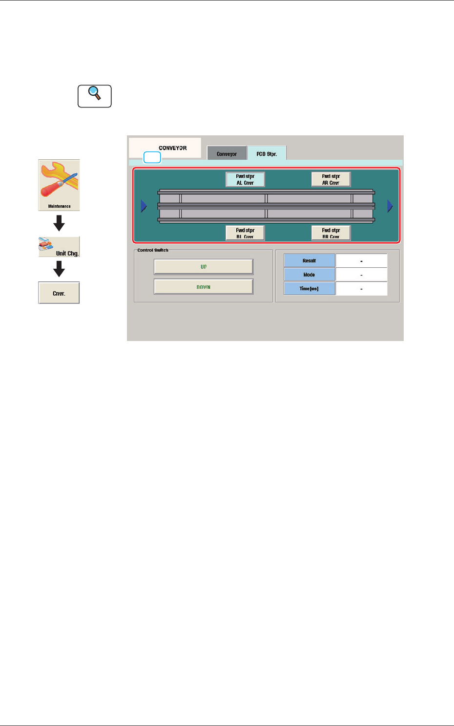
11.2 "PCB Stpr." Tab Sheet
This tab sheet enables the operator to adjust the PCB stopper for each lane
and each block.
Reference
Refer to "4.3.2 "PCB Stpr" Window" in Chapter 1, Volume 3, in the
SIGMA-G5 main machine instruction manual for the information other
than for dual transfer.
[1]
Fig. 21 PCB Stpr.
[1] Block selection Button
Using these buttons, the block in the lane where there is the PCB stopper to
be operated, is selected.
1103-001
11.2 "PCB Stpr." Tab Sheet
Graphic
Development
22
OM-1683
1103-001
12. Machine System
12. Machine System
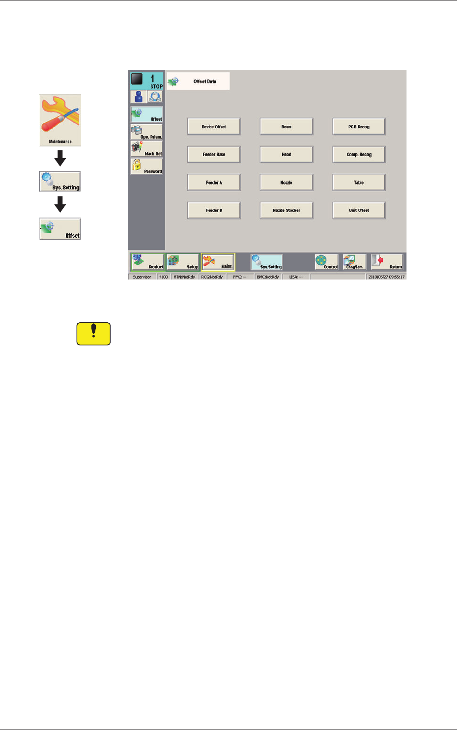
Fig. 22 Offset Data
Notice
Do not change the parameters unless necessary. These parameters
are factory-adjusted upon shipment of the machine.
Graphic
Development
23
OM-1683
1103-001
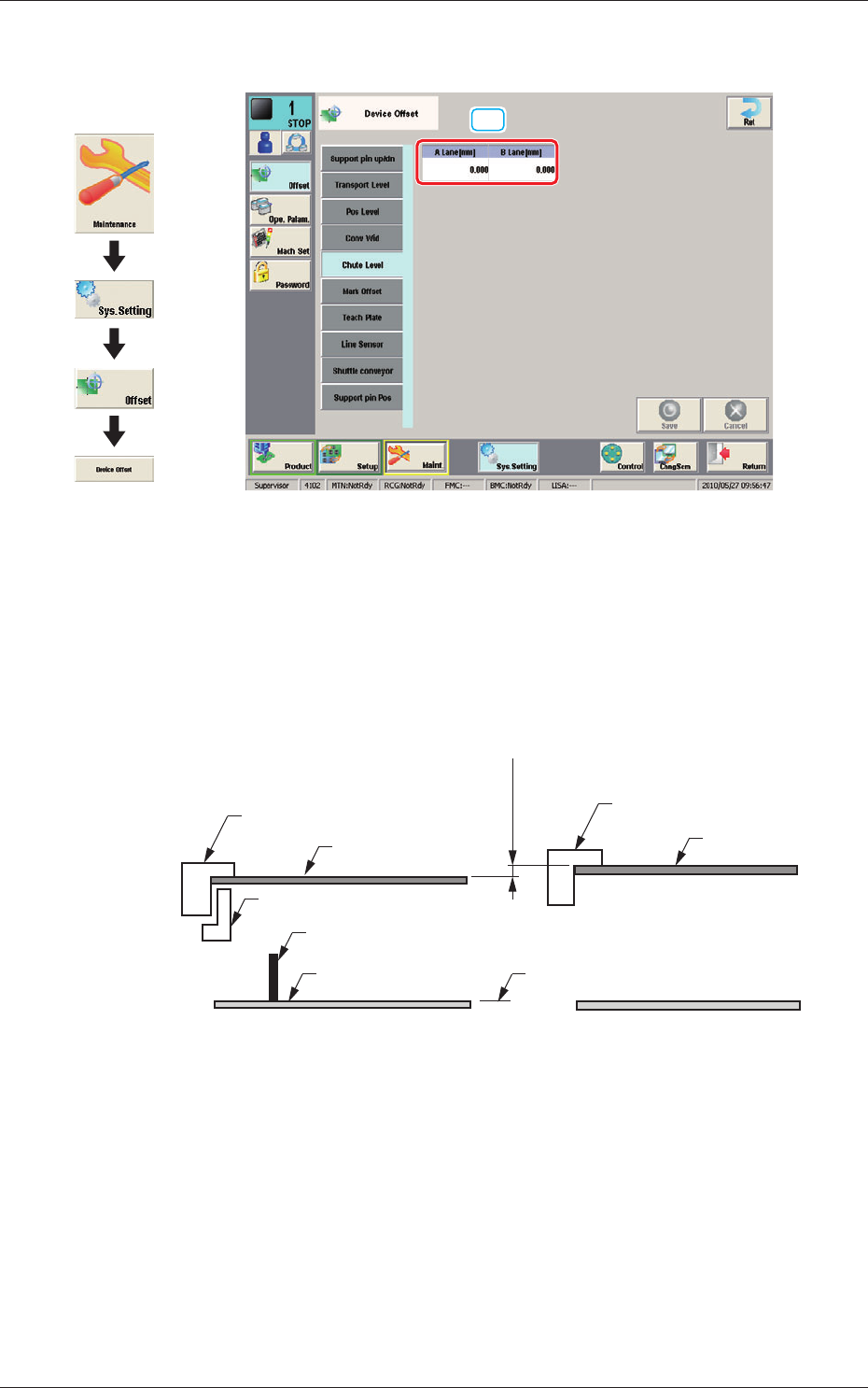
12.1 "Chute Level" Window
12.1 "Chute Level" Window
[1]
Fig. 23 Chute Level
[1] Chute Level
When the single transfer mode is setup and the PCB size is over 290 mm,
this offset is used to adjust the difference in the positioning height between
the lanes.
Lane A Chute Upper Surface
PCB
(-)
(+)
Support Pin
Backup Base
Difference
A-BL B-BL
Lane B Chute Upper Surface
PCB
2 Clamps
Origin
Fig. 24
Graphic
Development