OM-1273-004_w.pdf - 第118页
3-9 AJK-ML T-ID 2.1.2 Editing of T ray Step Information When a step No. is selected in the "T ray Step" edit window (Fig. C5-1), the "T ray Step Information" window appears, enabling the operator to e…
3-8
AJK-MLT-ID
(C03) Tray Step Data
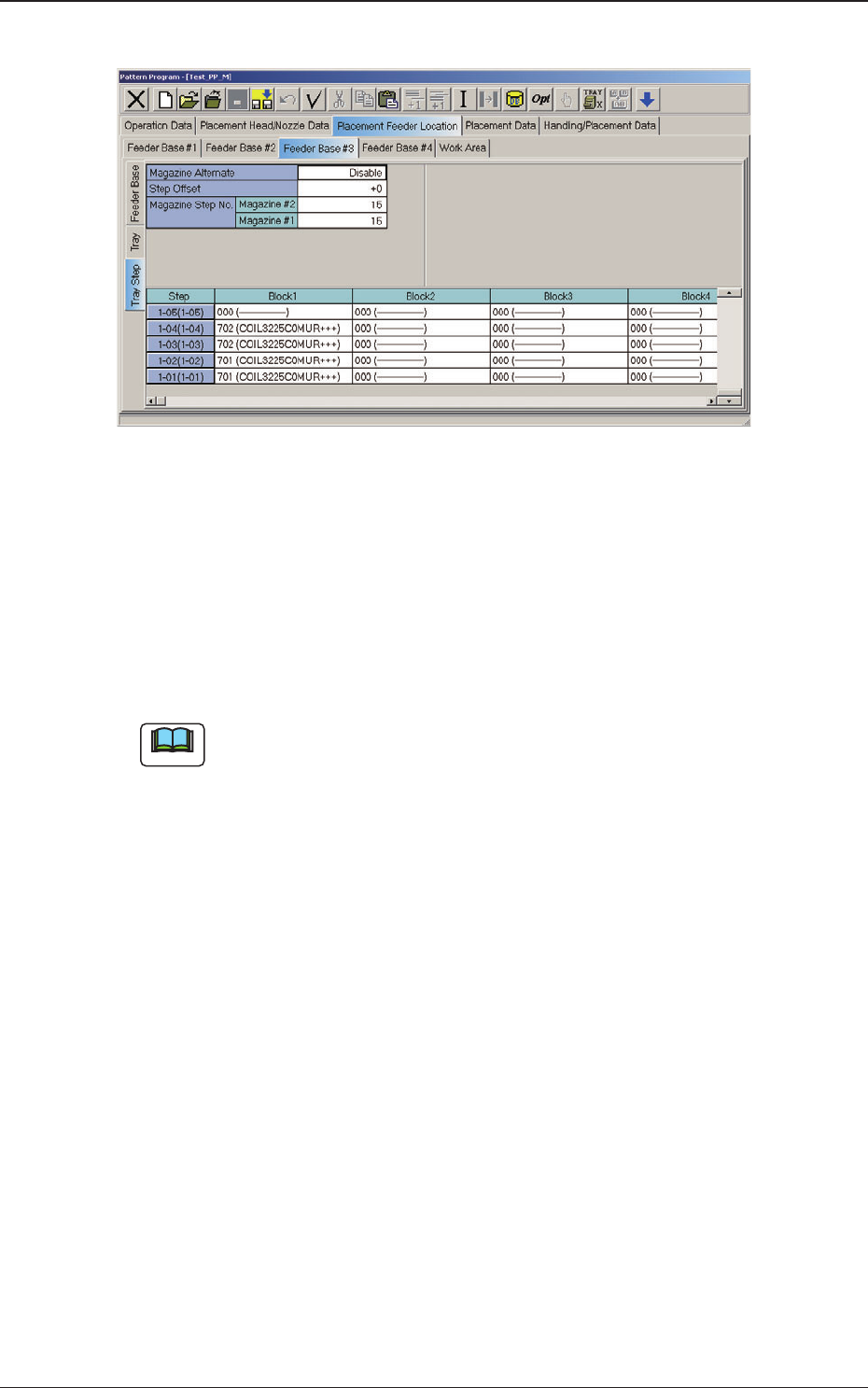
Fig. C5-1 "Tray Step" Edit Window
(C03_01) Magazine Alternate
This alternate function can be activated between Magazine #1 and #2 in
the same tray unit.
When "Enable" is set in the "Magazine Alternate" text box, the machine
continues running with the magazine (spare one) automatically changed
and set ready for use right after the previously connected magazine gets
empty of the components required by the main machine.
Note
(a) It is not necessary to equally allocate the component allocation spots
(step and block Nos.). The need for the spare steps and blocks, etc.,
can be determined freely for each individual magazines.
(b) The magazine alternate function is activated when a magazine gets
empty of the required types of components.
When components of the same type are set in several steps (stages),
the pallet alternate function is activated prior to this function.
(C03_02) Step Offset
Set the offset value for the component allocation to the multi-layer tray
feeder.
The
set parameter is added to the step No. designated in the step data.
(C03_03) Magazine Step No.
The number of magazine steps can be set for Magazines #2 and #1.
(C03_04) Step
Shown
are the step Nos. of the magazine.
The step Nos. have a button function. When one of these buttons is
pressed, the corresponding "Tray Step Information" window opens.
(C03_05) Block 1 through 9
Specify where in each step and block various components specied in
the tray data should be arranged.
2.1 Description of Pattern Program
0804-003

3-9
AJK-MLT-ID
2.1.2 Editing of Tray Step Information
When a step No. is selected in the "Tray Step" edit window (Fig. C5-1), the
"Tray Step Information" window appears, enabling the operator to edit the
tray step information.
[1] [2] [4][3] [5]
Fig. C6 "Tray Step Information [1-15 Step]" Window
[1] Block
Shown
are the block Nos.
[2] Fdr. No.
Displayed are the Nos. of the feeders arranged in each block.
[3] Position Offset status
Select "R", "L", or "Free Position" as Reference Point X for the block.
Position offset X [mm], Y [mm]
Enter the reference coordinates of the tray viewed from the pallet
reference position of each block.
[4] C
The
control commands can be selected.
[5] Component ID and Comment
Displayed are the component IDs entered in the "Tray" edit window and
the comments entered in the component library data.
2.1 Description of Pattern Program
0804-003
3-10
AJK-MLT-ID
3. Component Library
3.1 Carrier Data
This is a tab sheet which corresponds to all component shapes -
"Cylindrical", "Square", "Deform", "IC (Simple)", "IC (Complex)",
"Connector (Simple)", "Connector (Complex)", "Other Leaded (Simple)",
"Other Leaded (Complex)", and "BGA/CSP".
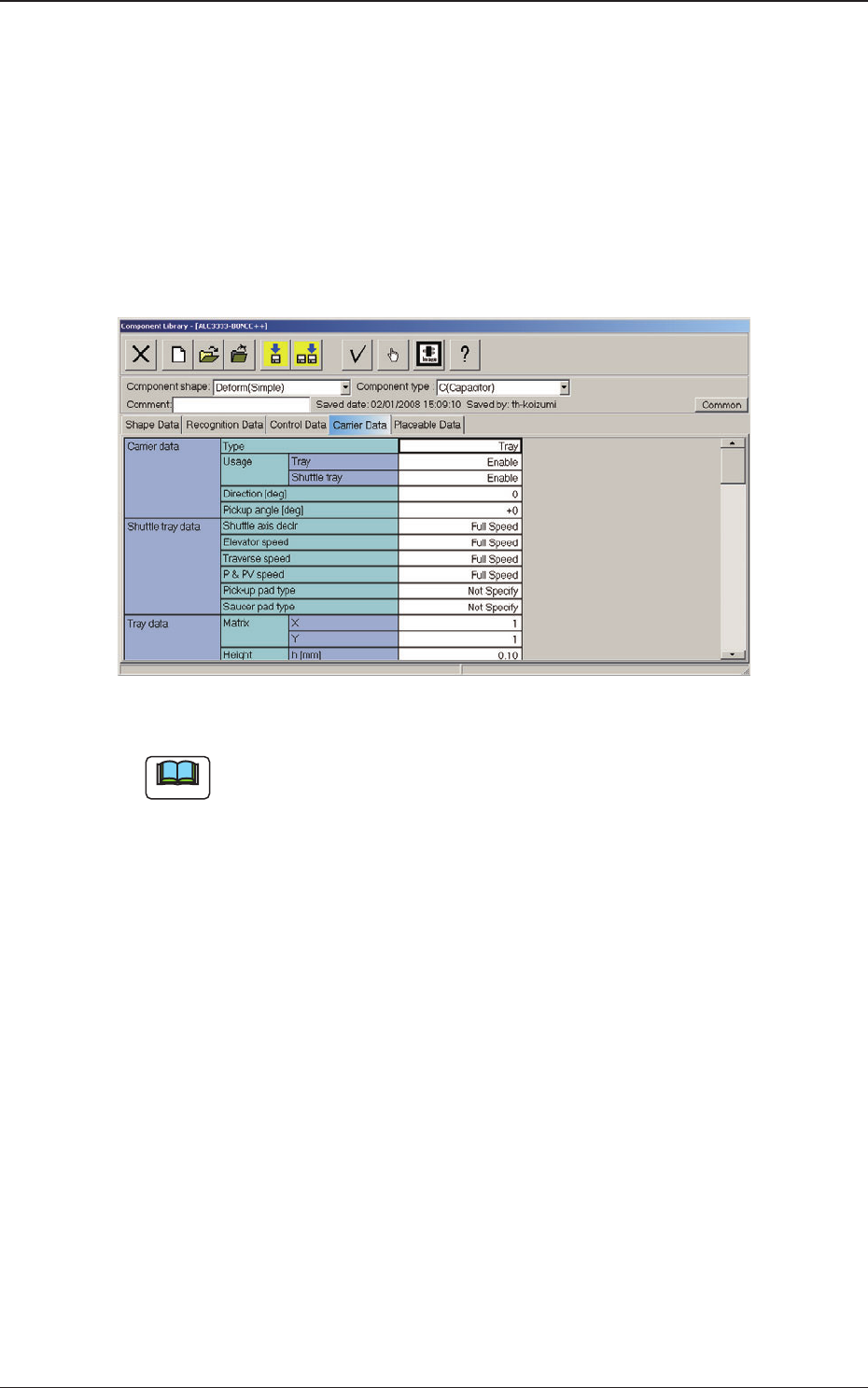
When the "Carrier Data" tab is pressed, the "Carrier Data" tab sheet appears.
Fig. C7 "Carrier Data" Tab Sheet (Type: Tray Selected)
Note
Refer to "2.3 (A03) Carrier Data" in "Chapter 2" of the instruction manual
"Component Library" for details of each data.
Set "Tray" in the "Type" text box of the label "Carrier data" and enter
parameters in the other text boxes of the label "Carrier data" and in the text
boxes of the label "Tray data".
3. Component Library
0804-003