OM-1273-004_w.pdf - 第196页
AJK-ML T-ID 5-33 Power Supply Section (Safety Circuit) 2 L 0706-002 -(M806WBL--5006) -1041 -1040 -1039 K1 K2 K1 K1 K2 K2 Control Circuit K2 K1 TH PWR 42 34 24 14 A2 A1 T1 1 T12 T21 T22 T31 T32 13 23 33 41 -1035 -1036 -10…
AJK-MLT-ID
5-32
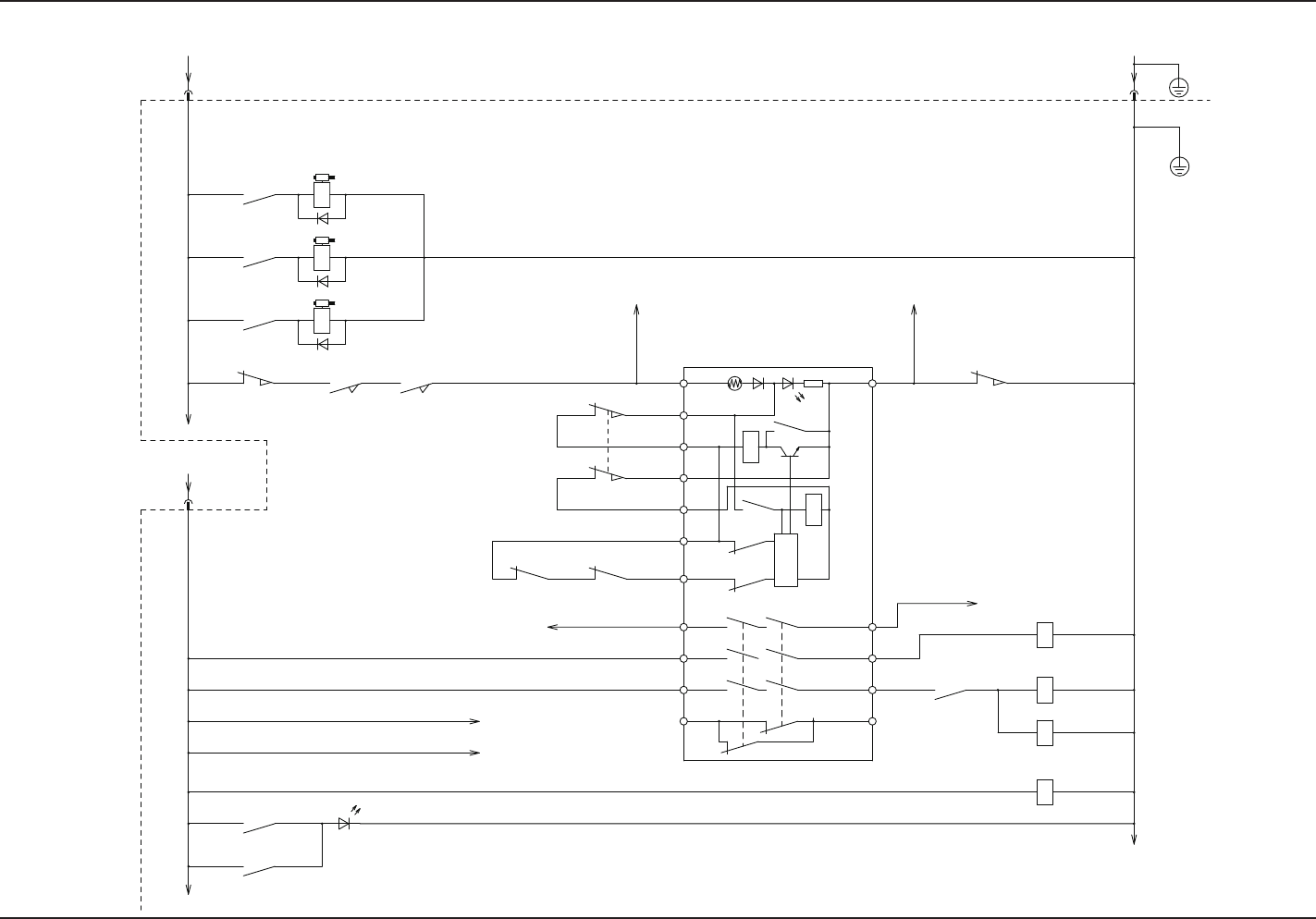
Power Supply Section (Safety Circuits) 1 L & R
0706-002 -(M806WBR--5005)
TNR-9G470K
-1022
-1012
-1021
-1020
24 34 42
13 413323T32T31T22
T12 T11
T21A1
14A2
PWR
TH
K1
K2
Circuit
Control
K2
K2
K1
K1
K2
K1
-1002
-1003
-1004
-1008-1009
-1010-1011
-1014-1013
-1005
-1015
-1006 -1007
-1017
-1018
-1019
-1016
-K201
73
913
-K501
-K503
-K202
A1 A2
A2A1
-K001
21 22
-K201-K202
2122
10A
-Y0101
51
-K507
62
-K508
-Y0102
3
-K509
7
-Y0103
1211
-S0503
12 11
-S0501
-S0501
2122
429
-K505
913
-S0504 -S0505
2221
-S0503
X502X502
24A1
X502
-H0001
1 5
-K505
-K506
62
-10A
-24A1
21 1 2
:02
:03
:01
Emergency Stop of
Main Body
From Main Body
of GX
Safety Door
Lock: Lower
Safety Door
Lock: Upper
Safety Door
Lock: (Magazine)
Safety Door Switch
(Magazine)
Maintenance Cover 1
Opening Detection
Maintenance Cover 2
Opening Detection
To Safety Relay K002: A2
To Safety Relay K002: A1
Safety Door Switch: (Magazine)
Safety Door Switch: (Lower)
Safety Door Switch: (Lower)
To -TR-U05 (UB14)
- X0524: 2
To Safety Relay K002: 23
To Safety Relay K002: 33
Power Lamp
To -TR-U05 (UB14)
- X0524: 1
EV1 Main Circuit
Power Supply ON
EV1 Load
Power Supply ON Check
EV (Lower)
4.2 Electrical Circuit Diagrams Power Supply Section (Safety Circuits) 1 L & R
AJK-MLT-ID
5-33
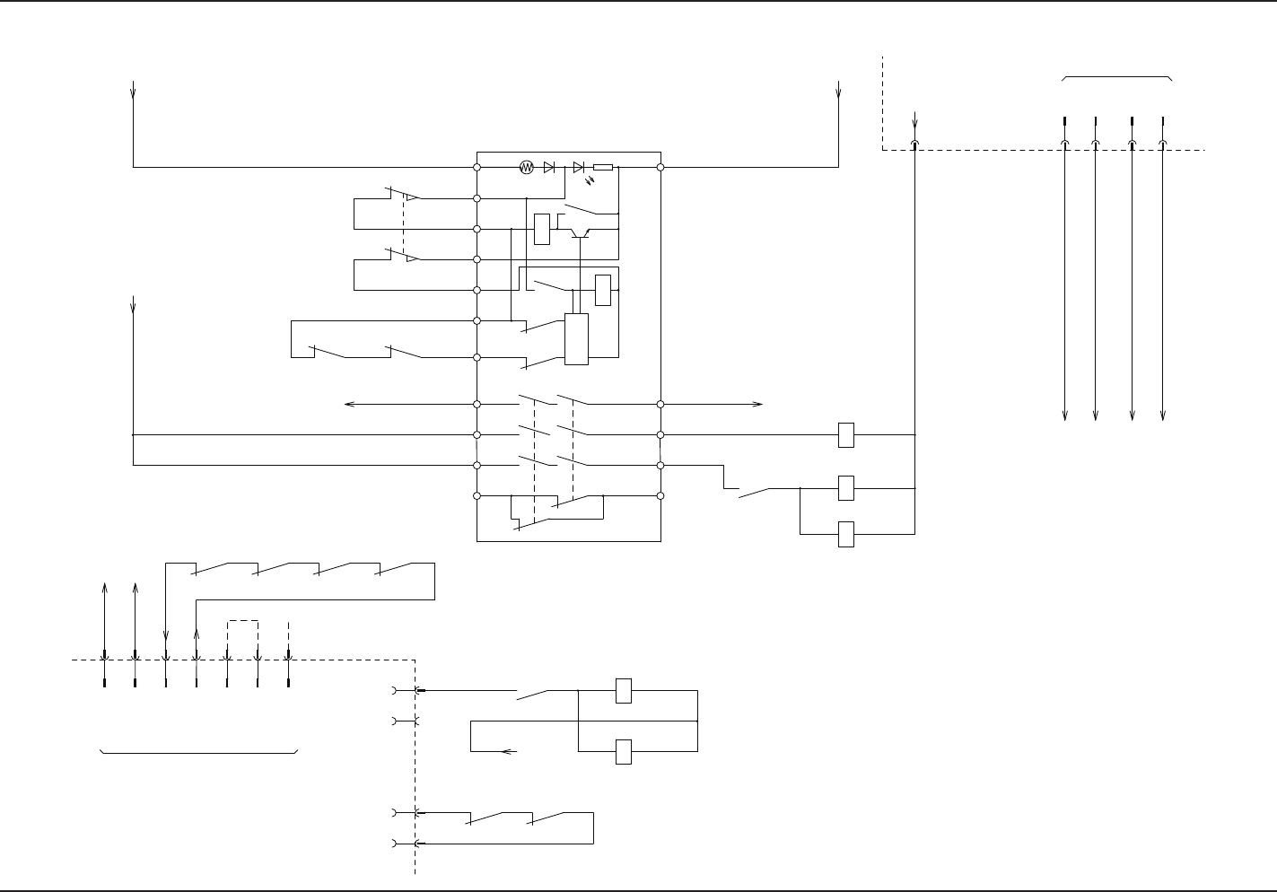
Power Supply Section (Safety Circuit) 2 L
0706-002 -(M806WBL--5006)
-1041
-1040
-1039
K1
K2
K1
K1
K2
K2
Control
Circuit
K2
K1
TH
PWR
42342414A2
A1
T11T12
T21 T22 T31 T32 13 23 33 41
-1035 -1036
-1033 -1032
-1031 -1030
-1034
-24G1
-10G
-10B
-24B1
-1037
-1038
-1044
-1042
-1043
-1001
-1028-1027-1026
-1029
-1025
-1023
-1024
-K301
14 10
-K506
84
-K504
-K302
A1 A2
A2A1
-1015
-K002
22 21
-S0502
-S0502
1112
22 21
-K302 -K301
2221
-1007 -1018
-10A
10A
24G1
10G
:4
:3
:1
:2
X503
10B
24B1
X502
:01
:02
:01
X507
:04
-K102-K101
2221 22 21
6 2
-K502
62616261
-K201 -K202
62
-K301
61
-K302
6162
:7
:3
:4
X504
:2
:1
:6
:5
A2A1
-K101
-K102
A2A1
10A
X507
COM
Safety Door Switch: (Upper)
Safety Door Switch: (Upper)
To -TR-U05 (UB14)
-X0525: 2
Emergency Stop
Detection
From X2639: 2
Main Body Safety
Cover Detection
From X2722: 2
Safety Relay K3
To X2622: 2
Safety Relay K3
From X2611: 6
Identification 1
Identification 2
From X20: 2
(Installation of Stage A)
From X23: 2
(Installation of Stage B)
From X20: 1
(Installation of Stage A)
From X23: 1
(Installation of Stage B)
From X36: 2
(Installation of Stage A)
From X37: 2
(Installation of Stage B)
From X36: 1
(Installation of Stage A)
From X37: 1
(Installation of Stage B)
From Main Body of GX
Traverse Main Circuit
Power Supply ON
From Terminal
EV2 Main Circuit
Power Supply ON
EV2 Load Power ON
Detection
To -TR-U05 (UB14)
-X0525: 1
EV (Upper)
From Main Body of GX
Relay 2 (UB21) Board
To K501-5
To -TR-U04( CN6: 2)
4.2 Electrical Circuit Diagrams Power Supply Section (Safety Circuit) 2 L
AJK-MLT-ID
5-34
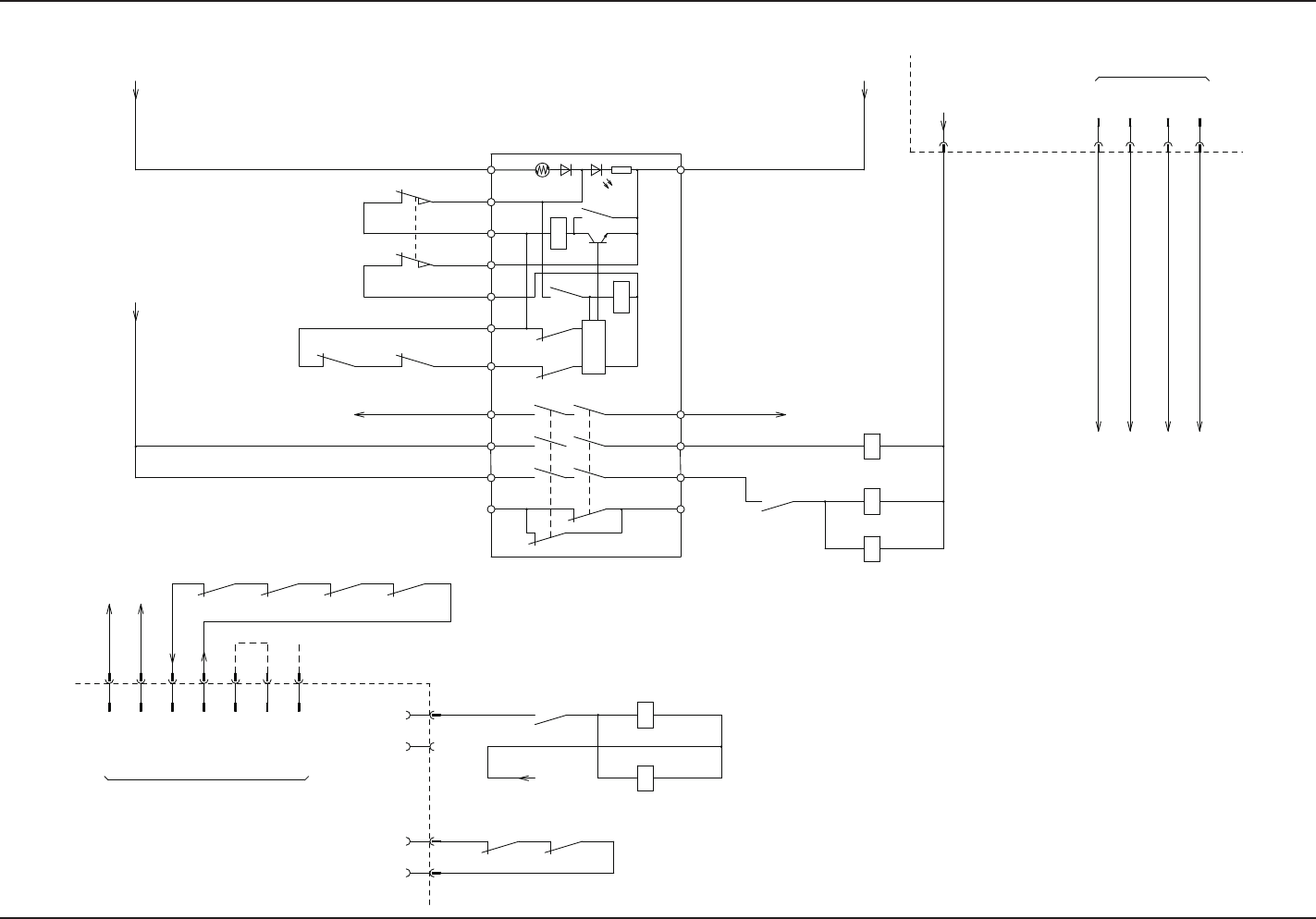
Power Supply Section (Safety Circuit) 2 R
0706-002 -(M806WBR--5006)
-1041
-1040
-1039
K1
K2
K1
K1
K2
K2
Control
Circuit
K2
K1
TH
PWR
42342414A2
A1
T11T12
T21 T22 T31 T32 13 23 33 41
-1035 -1036
-1033 -1032
-1031 -1030
-1034
-1024
-1023
-24G1
-10G
-10B
-24B1
-1025
-1029
-1026 -1027 -1028
-1037
-1038
-1001
-1043-1042
-1044
-K301
14 10
-K506
84
-K504
-K302
A1 A2
A2A1
-1015
-K002
22 21
-S0502
-S0502
1112
22 21
-K302 -K301
2221
:5
:6
:1
:2
X504
:4
:3
-1007 -1018
-10A
10A
24G1
10G
:4
:3
:1
:2
X503
10B
24B1
:7
62 61
-K302
61
-K301
62
-K202-K201
61 62 61 62
X502
:01
A1 A2
-K102
-K101
A1 A2
-K502
26
212221 22
-K101 -K102
:04
X507
:01
:02
10A
X507
COM
Safety Door Switch: (Upper)
Safety Door Switch: (Upper)
To -TR-U05 (UB14)
-X0525: 2
Emergency Stop
Detection
From X2639: 2
Main Body Safety
Cover Detection
From X2722: 2
Safety Relay K3
To X2622: 2
Safety Relay K3
From X2611: 6
Identification 1
Identification 2
From X20: 2
(Installation of Stage C)
From X23: 2
(Installation of Stage D)
From X20: 1
(Installation of Stage C)
From X23: 1
(Installation of Stage D)
From X36: 2
(Installation of Stage C)
From X37: 2
(Installation of Stage D)
From X36: 1
(Installation of Stage C)
From X37: 1
(Installation of Stage D)
From Main Body of GX
Traverse Main Circuit
Power Supply ON
From Terminal
EV2 Main Circuit
Power Supply ON
EV2 Load Power ON
Detection
To -TR-U05 (UB14)
-X0525: 1
From Main Body of GX
Relay 2 (UB21) Board
To K501-5
To -TR-U04( CN6: 2)
EV (Upper)
4.2 Electrical Circuit Diagrams Power Supply Section (Safety Circuit) 2 R