OM-1273-004_w.pdf - 第81页
2-16 AJK-ML T-ID [1] [2] [3] [4] Fig. B10 "Comp Crg Dt Edit" Window (3/4) [1] [2] [3] [4] Fig. B10-1 "Comp Crg Dt Edit" Window (4/4) 2.4 Production Data 0804-003
2-15
AJK-MLT-ID
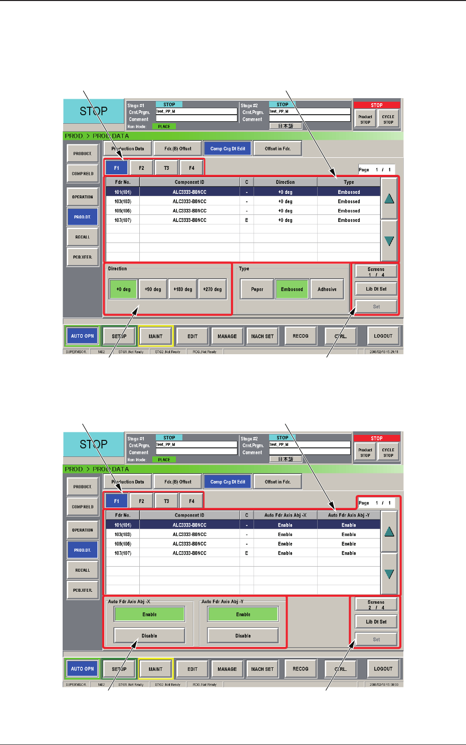
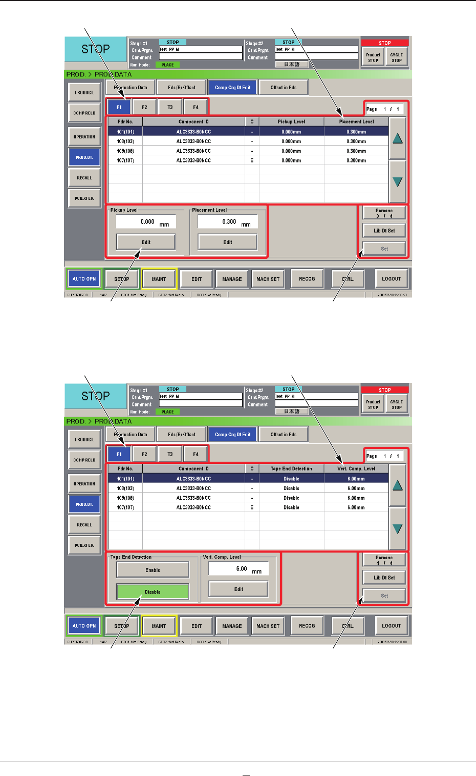
2.4.2 Component Carriage Data Editing
This window enables the operator to check and change the component
carriage data for the production model.
[1] [2]
[3] [4]
Fig. B8 "Comp Crg Dt Edit" Window (1/4)
[1] [2]
[3] [4]
Fig. B9 "Comp Crg Dt Edit" Window (2/4)
2.4 Production Data
0804-003
2-16
AJK-MLT-ID
[1] [2]
[3] [4]
Fig. B10 "Comp Crg Dt Edit" Window (3/4)
[1] [2]
[3] [4]
Fig. B10-1 "Comp Crg Dt Edit" Window (4/4)
2.4 Production Data
0804-003

2-16-1
AJK-MLT-ID
[1] Unit Selection Buttons
These buttons can be used to specify the feeder base whose carrier data
should be conrmed or changed.
[2] Information
Display
Displayed is the component carriage data of the feeder base (the multi-
layer tray feeder) selected in [1].
[3] Mode Buttons
These buttons are used to change the direction of component feed,
the auto feeder axis adjustment X and Y, the pickup level, and the
placement
level.
[4] [Screens #/3], [Lib Dt Set], and [Set] Buttons
[Screens #/3] Button :
This button can be used to open another page.
[Lid Dt Set] Button :
When pressed, this button resets the selected
component data to the defaults registered in
the component library.
[Set] Button :
When pressed, this button sets the changed
contents.
2.4 Production Data
0804-001