OM-1273-004_w.pdf - 第84页
2-18 AJK-ML T-ID 3.2 Device Check When the [DVC CHECK] button on the submenu bar of the "MAINT ." window is pressed, the "I/O DIAG" window appears as an initial one of the "DVC CHECK" window…
2-17
AJK-MLT-ID
3. Menus for Maintenance
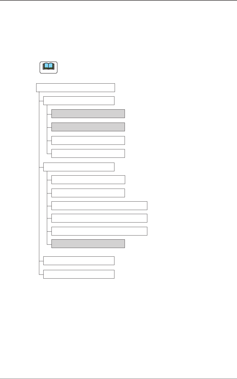
3.1 Outline of Menus for Maintenance
The following shows the hierarchical structure of the menus (including the
submenus and windows) for the maintenance operation.
Note
The shadowed (gray) items are related to the multi-layer tray feeder.
Menus for Maintenance Reference Item Nos.
Device Check
Input/Output 3.2.1
Motor 3.2.2
Recognition
Program
Information
Unit Adjustment
Linear Measure
Nozzle Change
Feeder Base & Feeder Connection
Cutting Adjustment
Conveyor PCB Stopper
Tray Unit 3.3.1
Device Test
Teaching
Fig.
B11 Outline of Menus for Maintenance
3. Menus for Maintenance
0706-002
2-18
AJK-MLT-ID
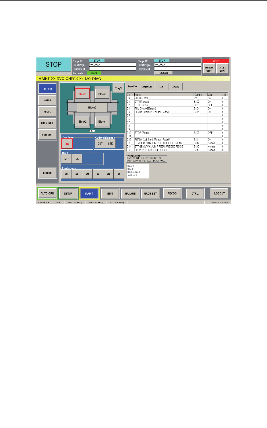
3.2 Device Check
When the [DVC CHECK] button on the submenu bar of the "MAINT."
window is pressed, the "I/O DIAG" window appears as an initial one of the
"DVC CHECK" window.
Fig. B12 "I/O DIAG" Window
3.2 Device Check
0804-003
2-19
AJK-MLT-ID
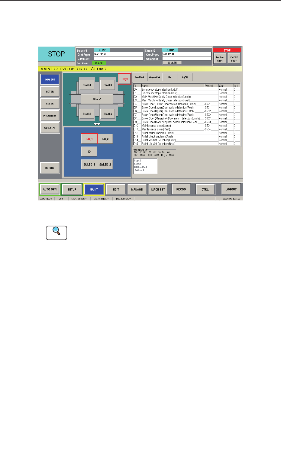
3.2.1 Input /Output
This window enables the operator to check the I/O signals and view the
status of each section.
Fig. B13 "INP / OUT" Window
Reference
Refer to "3.1 "I/O DIAG" Window" in "Chapter 4: Menus for
Maintenance" in the instruction manual (Volume 2: Operation) of the main
machine for details.
3.2 Device Check
0804-003