Nexus_en - 第8页
Inert gases and forming gas Nitrogen (N 2 ) is typically used to protect against oxidation. In combination with 5 % hydrogen, the forming gas is also used for reducing oxides; no special saf eguards are necessary within …
7
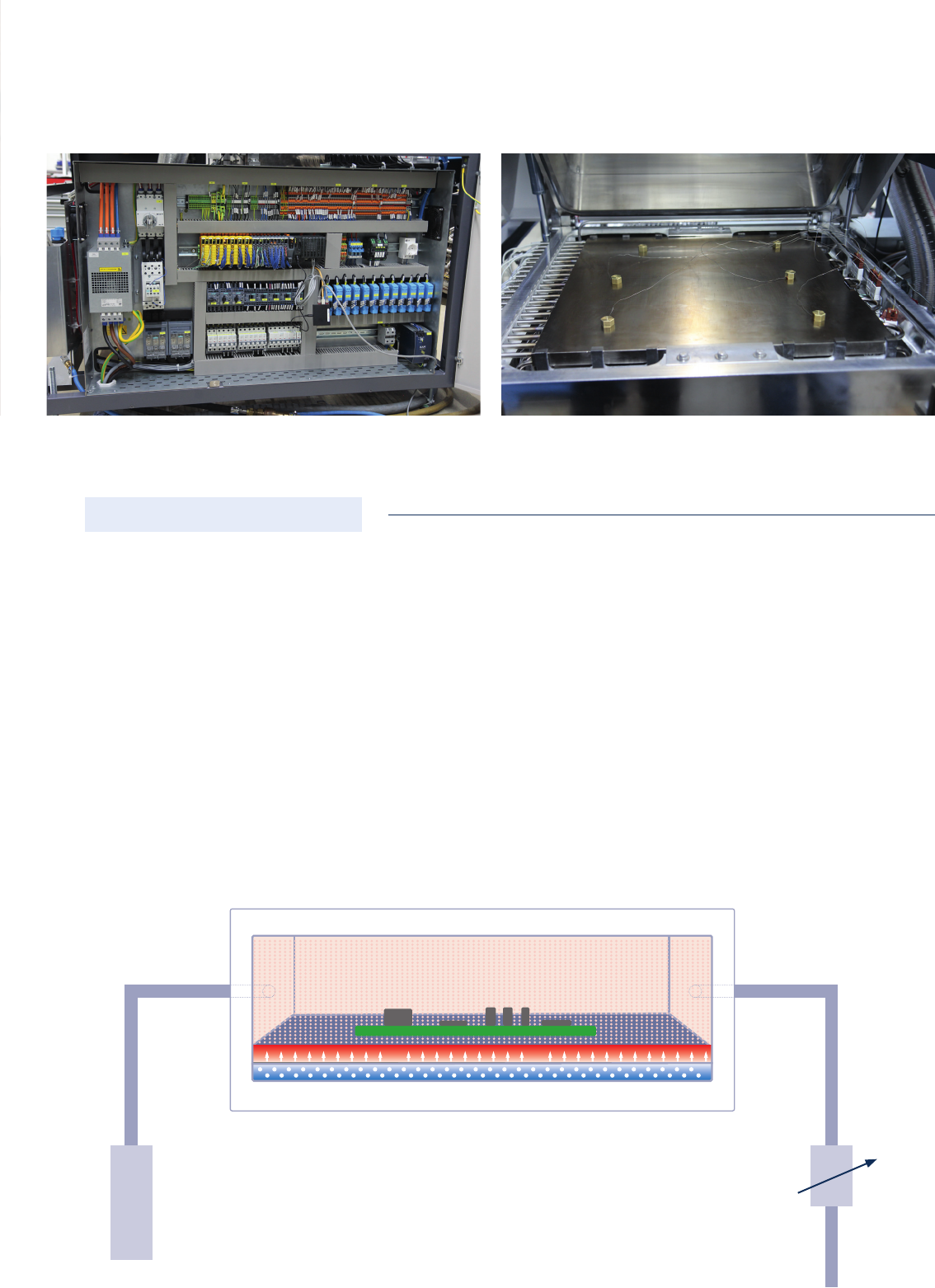
Controlled chamber pressure
A controlled gas sampling system via a vacuum pump from the process chamber prevents overpressure
during controlled flushing via a separate proportional valve for feeding into the process chamber; thus each
pressure level can be set as required using a software programme.
controlled chamber pressure with nitrogen atmosphere
pressure level constant
proportional valve
for nitrogen input
vacuum pump to control the chamber
pressure of 0 - 1000 mbar
Inert gases and forming gas
Nitrogen (N
2
) is typically used to protect against
oxidation. In combination with 5 % hydrogen, the forming gas
is also used for reducing oxides; no special safeguards are
necessary within this mixing ratio.
Forming gases with a hydrogen content from 5 % to 100 %
need necessarily appropriate safeguards and are used only at
280 °C or higher. Depending on the process temperature, the
use of formic acid can be benecial.
Activation (Gas)
Investment Wetting
Nitrogen N
2
Forming gas N
2
/H
2
(95 %/5 %)
Hydrogen H
2
100 %
Formid acid HCOOH
N
2
N
2
/H
2
Various media
for a wide range of requirements and demands
Depending on the process temperature and the desired oxide freedom, the use of different process media is possible.
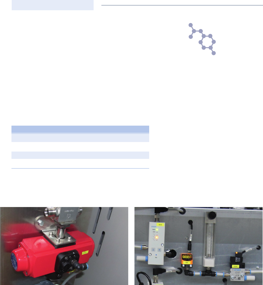
Formic acid tank (bubbler)
To achieve a stable, reliable, flux-free soldering process, the inert carrier gas (N
2
) is enriched with formic acid (HCOOH) and
transferred into the process chamber. So that the “saturation” of the carrier gas with formic acid remains constant, it is neces-
sary to keep the parameters constant while the liquid formic acid is flowing through. These include the flow velocity, flow rate,
temperature and the lling capacity of the formic acid tank (bubbler). Thanks to today’s control engineering, the nitrogen flow
rate can be monitored easily and reliably. Unlike the ll level of formic acid in conventional bubbler solutions which must be
manually relled with acid – taking into account the protective measures for employees – and here are subject to a greater
fluctuation in the lling capacity. This is not the case for this new generation of bubblers which monitor and readjusts the ll
level. This allows a stable process, and also increases the safety of employees, because original containers (standard 10 l)
with formic acid can be inserted into the housing of the bubbler without decanting. To make the device even safer, the housing
is monitored and equipped with its own suction system.
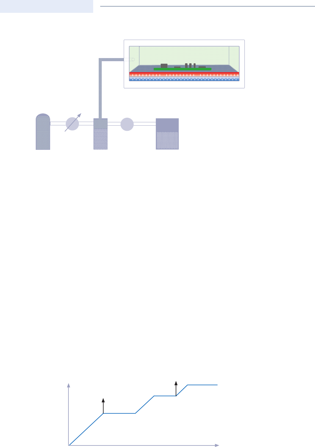
The removal of the oxides on metals with formic acid is performed using a two-step process; the schematic sequence of
this process can be seen in the following diagram. During the rst step, so-called formates of the metal are formed and the
formates are decomposed (Cu) or vaporised (SnO, SnO
2
) at approx. 200 °C. The H+ formed during the second step supports
oxide removal as well as the molten solder from the melting temperature in the reductive environment. This allows for a highly
wettable surface on copper and other metals. The application is suitable from process temperatures upwards of 200 °C.
controlled chamber pressure with nitrogen atmosphere
pressure level constant
formic acid tank (bubbler)
pump
proportional valve
or mass ow controller
HCOOH
N2
0 °C
150 °C
200 °C
SnO
2
+ 2 H - COOH Sn + CO
2
+ H
2
O
SnO
+ H - COOH Sn + CO
2
+ H
2
O + H
2
M - COOH
2
M + 2CO
2
+ H
2
MO + 2H - COOH M - (COOH)
2
+ H
2
O