00196376-0102_UM S-Feeder_EN.pdf - 第67页
Linear Vibratory Feeder, Type 3 Overview of Component Stick Magaz ines by Components Component Stick Magazines User Manual SIPLACE S-Feeder 67 4.2.1 Overview of Component Stick Magazines by Components The following table…

Linear Vibratory Feeder, Type 3
Component Stick Magazines
66 User Manual SIPLACE S-Feeder
▪ Component stick magazines can be refilled without the machine being stopped, as the refill opening
is located outside the protective cover on the placement machine.
▪ The length of component stick magazines is designed to completely accommodate all component
packaging magazines currently available on the market.
▪ Most component stick magazines have an approx. 12 cm red marking (2) next to the pickup position,
which tells the operator when components need to be refilled at the latest. The component stick
magazines should therefore always be refilled at least up to the far end of the red marking.
▪ The item number of each stick magazine is marked on the underside of the magazine end for easier
identification.
▪ To increase the function reliability, the component stick magazines are fixed to the basic feeder part
with small pins (5 6) at both ends of the vibratory feeder.
To profit from this increased function reliability, always make sure that the component stick maga-
zines are fitted correctly at the back and then at the front on the vibratory feeder.
▪ The new fixing pieces are designed to fit all magazine sizes, so that there is no need to replace the
fixing piece when you change the magazine.
▪ Vibratory feeders of previous series can be retrofitted for use with the new fixing pieces. The retro-
fitting kit can be ordered with the Item No. 00310741-xx.
A retrofitted vibratory feeder can also accommodate older magazine models.
▪ To facilitate pickup of special components, the pickup position (1) is raised above the magazine
guidance by 0.3 mm.
WARNING
The long component stick magazines protrude above the tape container and out of the place-
ment machine. There is a risk of injury at the unprotected, sharp edges of the component stick
magazine.
Only use component stick magazines with protective "bumper" edges.
Fit any unprotected component stick magazines with protective edges.
Protective edges can be ordered from the spare parts catalogue.
The fitting of protective edges is described in the "Retrofitting Guide for Protective Edges on
Vibratory Feeders", Item No. 00192925-xx.

Linear Vibratory Feeder, Type 3
Overview of Component Stick Magazines by Components Component Stick Magazines
User Manual SIPLACE S-Feeder 67
4.2.1 Overview of Component Stick Magazines by Components
The following table gives an overview of the different stick magazines and lists the components with
which each can be used.
Component Item No. Component Item No.
PLCC18 00311189-01 SockelPLCC20 00316400-01
PLCC20/28R 00311188-02 Sockel PLCC28/32 00315880-01
PLCC28/32 00311187-02 Sockel PLCC44, width 22 mm 00314750-01
PLCC32R 00320319-01 Sockel PLCC44, width 23.3 mm 00317310-01
PLCC44 00310839-02 Sockel PLCC52 00311997-01
PLCC52 00310848-01 Sockel PLCC68 00315878-01
PLCC68 00311012-02 Sockel PLCC84 00311967-01
PLCC84 00310851-01 SOJ26/20 00311007-02
SO6/8 00310509-02 SOJ28 00311182-01
SO8, height 2.4 mm 00314265-01 SOJ32, width 11.2 mm 00316805-01
SO8L/14L 00314264-01 SOJ32, width 8.66 mm 00322665-01
SO8M/10M SSOP14/20 00318324-01 SOT223 00346219-01
SOP10 Power 00317234-01 TLP113 00348511-01
SO10M/14M 00315923-01 TSSOP14/20, width 6.4 mm 00343788-01
SO14/16 00310510-02 TSSOP24, width 6.4 mm 00336656-01
SO16L/20L 00310508-02 TSSOP48/64, width 8.1 mm 00336067-01
SO16M/20M 00315167-01 TO252 Dpack 00357992-01
SO24L/28L 00310511-02 TO263 / SOT404 D²pack 00357994-01
SO24W/28W 00323635-01 VSO40 00311186-01
SO 32Y 00312061-01 VSO56 00314739-01
SOP44 00310940-01
SSOP14/16, width 6.0 mm 03070399-01
SSOP14/16, width 7.8 mm 03069925-01
Linear Vibratory Feeder, Type 3
Operating the Vibratory Feeder Setting the Vibratory Feeder
68 User Manual SIPLACE S-Feeder
4.3 Operating the Vibratory Feeder
4.3.1 Setting the Vibratory Feeder
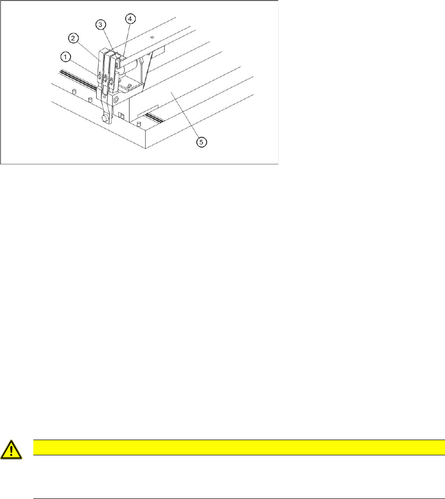
Front view with magnetic strip
4.3.1.1 Setting the Vibrator Flaps
The vibrator flaps (2) on the front of the device stop the components from falling out of the pickup position
during the vibration phase. Set the height of the flaps so that there is a gap between the component in
the pickup position and the closed flaps but so that this gap is not large enough for the components to
jump out. If the components are lower than the profile height of the component stick magazine at the
pickup position, set the gap between the flaps and the upper edge of the notch on the stick magazine.
►Loosen the hexagon socket-head screws (1).
►Move the flaps in their slots until they are positioned as required.
►Fasten the hexagon socket-head screws again.
Legend:
1 Hexagon socket-head screw for setting the air gap
2 Vibrator flap
3 Limiter
4 Centering piece
5 Body
CAUTION
Make sure that components or the component stick magazine do not touch the vibrator flaps
as this will have a negative influence on the vibration function.
Vibrator flaps are set correctly if they do not vibrate when the vibrator operates.