00196376-0102_UM S-Feeder_EN.pdf - 第50页
Tape Feeder Modules Details for 24/32, 44, 56, 72 and 88 mm S or S DP Inserting the Tape 50 User Manual SIPLACE S-Feeder 2.4.2.1 Inserting the Cover Tape in the Foil Removal ► (1) Close the pickup window, press it slight…
Tape Feeder Modules
Inserting the Tape Details for 24/32, 44, 56, 72 and 88 mm S or S DP
User Manual SIPLACE S-Feeder 49
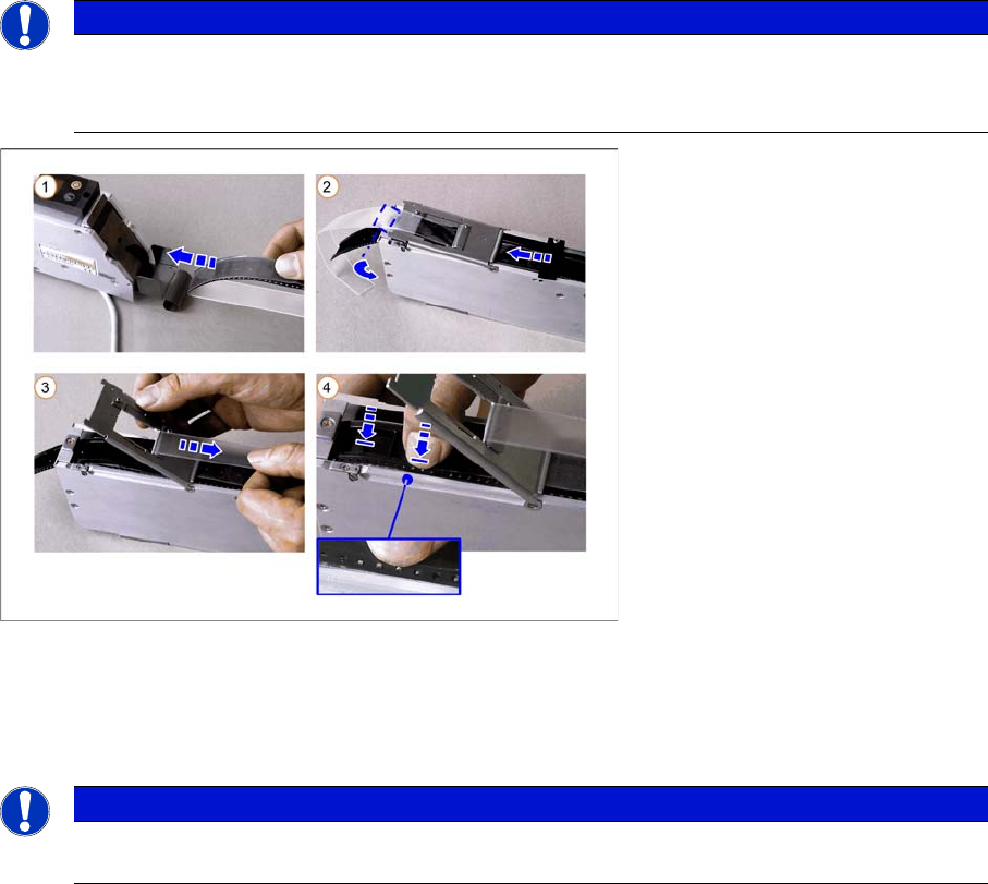
2.4.2 Inserting the Tape
►
Only for tapes with foil overhang at the beginning of the tape:
Wrap the foil overhang (for threading in) around the beginning of the tape material, tension the foil
along the underside of the tape and hold in place.
►(1) Thread the tape from behind into the feeder track.
► (2) Open the pickup window:
To do this, press the pickup window down slightly and the turn the latch by 90°, until this engages
audibly.
Now push the tape under the pickup window.
Only for tapes with no overhang at the beginning of the tape:
Free up approx. 2-3 cm of the foil and fold the foil back.
►(3) Lift the pickup window and pull the cover tape backwards, over the removal edge.
Now press the removal edge down.
►(4) Make sure that the tape perforations are in the transport wheel before you close the removal edge.
NOTICE
Before inserting a new tape, check that the step size is set correctly.
Before you insert the tape, remove any loose components from the feeder. Pay particular
attention to the areas below the removal edge and the pickup window.
NOTICE
For 24/32 mm S feeders when processing tapes with a width of 24 mm:
Make sure that the tape is threaded through the tape clip when you feed it in.
Tape Feeder Modules
Details for 24/32, 44, 56, 72 and 88 mm S or S DP Inserting the Tape
50 User Manual SIPLACE S-Feeder
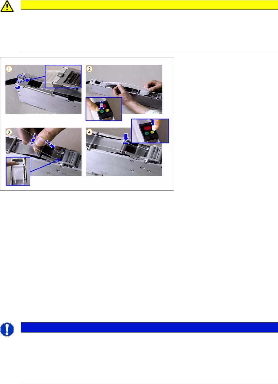
2.4.2.1 Inserting the Cover Tape in the Foil Removal
►(1) Close the pickup window, press it slightly downwards and hold.
Rotate the latch by 90° into its central position, so that it engages audibly. The pickup window is now
locked in place.
►(2) Press the green "Index" button until the tape comes out of the front of the feeder and then pull the
foil approx. 30 cm back.
►(3) Place the beginning of the foil over the foil rocker and then hold it between the two combing
toothed wheels of the foil removal device.
►(4) Press the yellow "Foil" button on the control unit and hold until the motor is switched off auto-
matically.
While you hold the button pressed and as long as the foil rocker is not tensioned, the motor will con-
tinue to draw in the foil. As the motor is not operated with full power in this case, you can adjust the
drawing in speed by gently tugging on the foil.
Make sure that the foil lies flat between the toothed wheels, that it has no folds and that it is not pulled
away to the sides of the toothed wheels.
CAUTION
Make sure that you remove the adhesive strip at the beginning of the cover tape overhang on
the new tapes. The adhesive strip could otherwise damage the foil removal. The same applies
to torn splice points. Remove any remaining adhesive strips here, before you feed the foil into
the foil container.
Do not tear the foil as a stretched foil could lead to malfunctions at the foil removal point.
NOTICE
Once the tape has been inserted and the cover tape tensioned, the pickup window may no long-
er be unlocked without first relieving the tension on the foil (by pressing rocker 2 and then wait-
ing until the foil motor has switched off). Nonobservance of this will cause the tape to be torn
out of its perforations by the tension applied to the foil and it to be moved forward by several
pockets.
The result: component losses and possible malfunctions from loose components.
Tape Feeder Modules
Setting the Step Size Details for 24/32, 44, 56, 72 and 88 mm S or S DP
User Manual SIPLACE S-Feeder 51
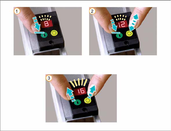
2.4.3 Setting the Step Size
To set the step size, proceed as follows:
►(1) Press the green "Index" button and hold until the LED display begins to flash. Continue to hold the
button pressed.
►(2) Press the yellow "Foil" button several times until the control unit display shows the required step
size in mm. The step size is increased by 4 mm each time you press the button.
If you accidentally exceed the required size, you can correct the setting using one of the following
options:
⇨ Press the yellow "Foil" button frequently, until the required step size is shown in the control unit
display.
Alternatively:
⇨ While you are in setting mode (display flashes), you can let go of the button and then press the
green button again (within one second) to reverse the direction of counting. The step size will
now be reduced by 4 mm each time you press the button.
You can reverse the direction of counting as often as you wish.
►Release both buttons.
The setting procedure is finished when the flashing display changes to a permanent display.
For an overview of the available step sizes, refer to "1.3 Technical Data" [ ➙ 10].