00196376-0102_UM S-Feeder_EN.pdf - 第69页
Linear Vibratory Feeder, Type 3 Setting the Vibratory Feeder Operating the Vibratory Feeder User Manual SIPLACE S-Feeder 69 4.3.1.2 Recommended Vibration Times for Setting Up Components ► Open the main menu in the line c…
Linear Vibratory Feeder, Type 3
Operating the Vibratory Feeder Setting the Vibratory Feeder
68 User Manual SIPLACE S-Feeder
4.3 Operating the Vibratory Feeder
4.3.1 Setting the Vibratory Feeder
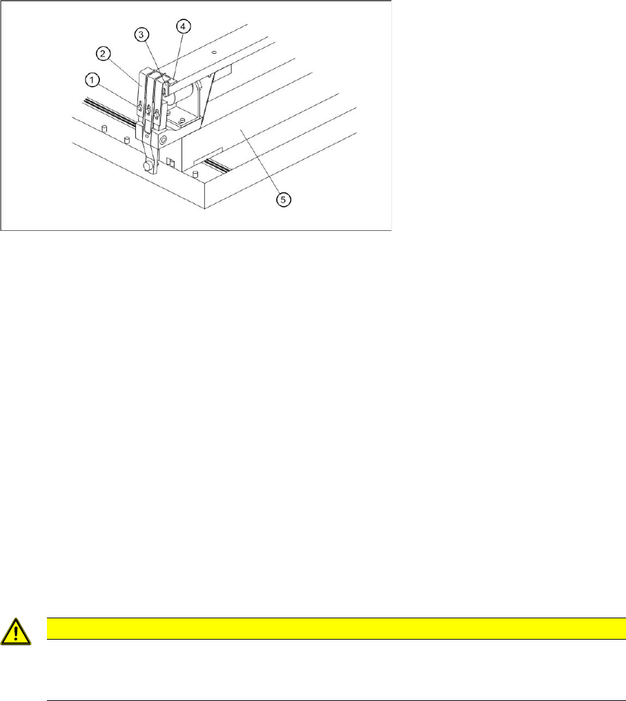
Front view with magnetic strip
4.3.1.1 Setting the Vibrator Flaps
The vibrator flaps (2) on the front of the device stop the components from falling out of the pickup position
during the vibration phase. Set the height of the flaps so that there is a gap between the component in
the pickup position and the closed flaps but so that this gap is not large enough for the components to
jump out. If the components are lower than the profile height of the component stick magazine at the
pickup position, set the gap between the flaps and the upper edge of the notch on the stick magazine.
►Loosen the hexagon socket-head screws (1).
►Move the flaps in their slots until they are positioned as required.
►Fasten the hexagon socket-head screws again.
Legend:
1 Hexagon socket-head screw for setting the air gap
2 Vibrator flap
3 Limiter
4 Centering piece
5 Body
CAUTION
Make sure that components or the component stick magazine do not touch the vibrator flaps
as this will have a negative influence on the vibration function.
Vibrator flaps are set correctly if they do not vibrate when the vibrator operates.
Linear Vibratory Feeder, Type 3
Setting the Vibratory Feeder Operating the Vibratory Feeder
User Manual SIPLACE S-Feeder 69
4.3.1.2 Recommended Vibration Times for Setting Up Components
►Open the main menu in the line computer software and select the vibratory feeder location.
►Select the vibratory feeder setup.
►Select the component in the vibratory feeder.
►Select the menu item "
Services
".
►Select the menu item "
Packaging box
" and enter the vibration time according to the following table.
►Confirm the entry and save the data.
4.3.1.3 Centering Pieces for Aluminum Stick Magazines
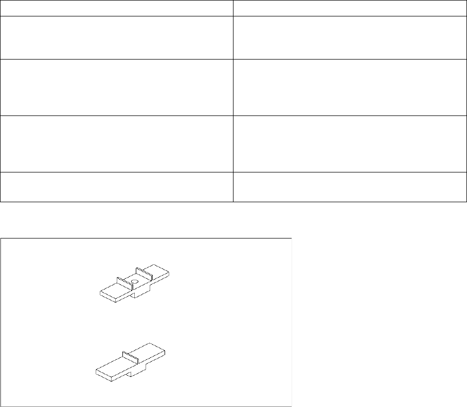
Centering pieces
The vibratory feeder type 3 is supplied with two centering pieces (9.5 and 15 mm). These centering
pieces position the component stick magazines correctly at the pickup position. The centering piece
used depends on the width of the stick magazine. Centering pieces are not required with stick magazines
which are wider than 15 mm.
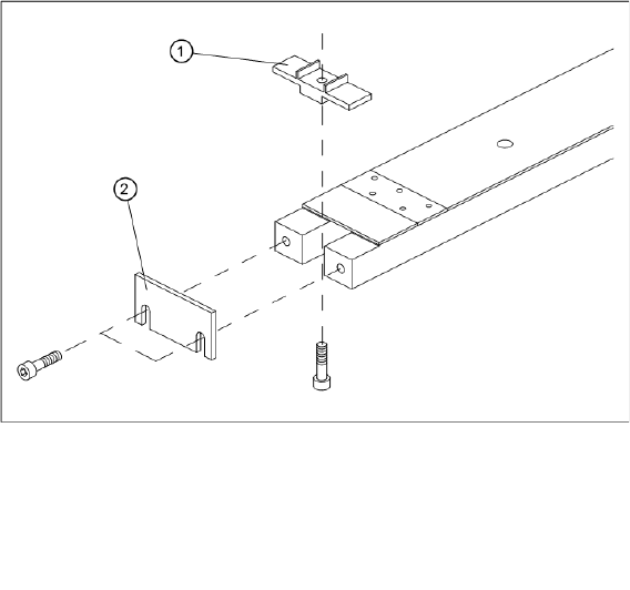
The centering pieces are fixed to the vibratory feeder with a screw (see diagram).
Vibration time in the Packaging Editor (ms) Components
400 - 600 SO6
SO8
SO14
600 - 800 SO16
SOL20
PLCC20
PLCC28
800 - 1000 SOL28
SOJ20
SOJ28
PLCC44
> 1000 PLCC68
PLCC84
Linear Vibratory Feeder, Type 3
Operating the Vibratory Feeder Setting the Vibratory Feeder
70 User Manual SIPLACE S-Feeder
Fitting the centering pieces
Legend:
1 Centering piece
2 Limiter