00196376-0102_UM S-Feeder_EN.pdf - 第70页
Linear Vibratory Feeder, Typ e 3 Operating the Vibratory Feeder Setting the Vibratory Feeder 70 User Manual SIPLACE S-Feeder Fitting the centering pieces Legend: 1 Centering piece 2 Limiter
Linear Vibratory Feeder, Type 3
Setting the Vibratory Feeder Operating the Vibratory Feeder
User Manual SIPLACE S-Feeder 69
4.3.1.2 Recommended Vibration Times for Setting Up Components
►Open the main menu in the line computer software and select the vibratory feeder location.
►Select the vibratory feeder setup.
►Select the component in the vibratory feeder.
►Select the menu item "
Services
".
►Select the menu item "
Packaging box
" and enter the vibration time according to the following table.
►Confirm the entry and save the data.
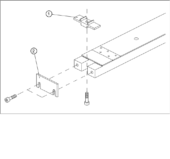
4.3.1.3 Centering Pieces for Aluminum Stick Magazines
Centering pieces
The vibratory feeder type 3 is supplied with two centering pieces (9.5 and 15 mm). These centering
pieces position the component stick magazines correctly at the pickup position. The centering piece
used depends on the width of the stick magazine. Centering pieces are not required with stick magazines
which are wider than 15 mm.
The centering pieces are fixed to the vibratory feeder with a screw (see diagram).
Vibration time in the Packaging Editor (ms) Components
400 - 600 SO6
SO8
SO14
600 - 800 SO16
SOL20
PLCC20
PLCC28
800 - 1000 SOL28
SOJ20
SOJ28
PLCC44
> 1000 PLCC68
PLCC84
Linear Vibratory Feeder, Type 3
Operating the Vibratory Feeder Setting the Vibratory Feeder
70 User Manual SIPLACE S-Feeder
Fitting the centering pieces
Legend:
1 Centering piece
2 Limiter
Linear Vibratory Feeder, Type 3
Setting the Vibratory Feeder Operating the Vibratory Feeder
User Manual SIPLACE S-Feeder 71
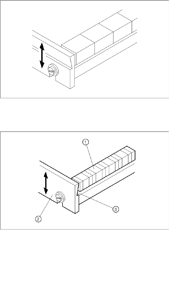
4.3.1.4 Setting the Limiter
The limiter below the vibrator flaps needs to be set to the height of the components used.
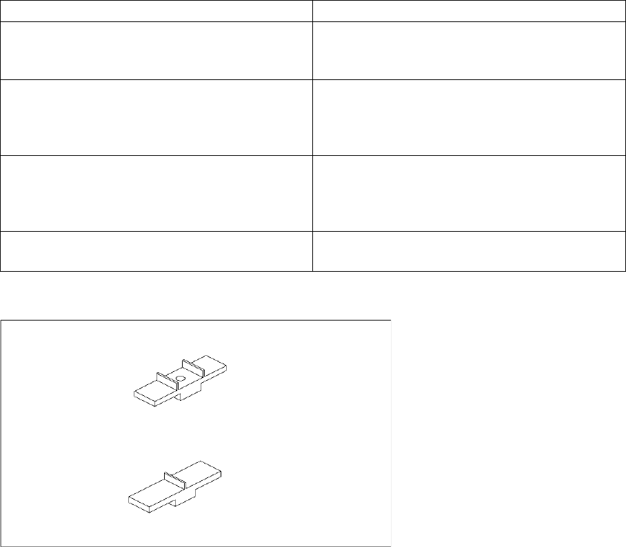
The notch at the back of the limiter ensures that you can easily remove the components and prevents
small components from being sucked up against the component stick magazine.
When using larger components, such as SO14, the back notch on the limiter points towards the front,
away from the component.
Position of limiter when using larger components
When using smaller components, the back notch on the limiter points towards the back, with the edge
towards the component.
Position of limiter when using smaller components
►To set the limiter, loosen the two screws on the front of the vibratory feeder.
►Turn the limiter into the correct position for the component used.
►Fix the limiter into place with the two screws.
Legend:
1 Component
2 Limiter
3 Back notch