00196376-0102_UM S-Feeder_EN.pdf - 第77页
Dip Module Hand Guards User Manual SIPLACE S-Feeder 77 5.4 Hand Guards The DIP module is set up like a feeder on the changeover table. As with a feeder, the DIP module needs to be protected above to preven t unauthorized…

Dip Module
Safety Instructions
76 User Manual SIPLACE S-Feeder
5.3 Safety Instructions
The placement machines in the SIPLACE family are powered by mains voltage. Parts of the machine
may therefore conduct dangerous voltage levels. This electricity is present at certain assemblies inside
the machine even when the main switch is switched off!
Incorrect use of the machine or touching live machine parts can cause fatal or severe injuries and con-
siderable damage to equipment.
After you have shut the operating system down properly and before you perform any work on the
machine, make sure that the placement machine has been turned off at the main switch and is isolated
from the mains power supply. In addition, the compressed air supply must be turned off at the main valve
of the compressed air unit in the machine base and the compressed air lines need to have been bled by
actuating the needle valve at the compressed air unit.
Danger: persons wearing a heart pacemaker are not permitted to work near linear motors, as described
in detail in the placement machine operating and service manuals, chapter "Special Safety instructions
for Working in the Vicinity of Powerful Magnetic Fields".
Observe the applicable accident prevention regulations, DIN standards and special safety regulations
applicable for your country at all times.
Observe the ESD regulations and the instructions about residual voltage in the chapter "Operating
safety" of the operating manual.
Before performing any retrofitting work on the placement machine, secure it to prevent unauthorized
reactivation or use by other persons.
There is an additional, higher risk of accidents when working with the SITEST program. The SITEST
program may therefore only be started by specially authorized and trained persons.
WARNING
The safety instructions in the chapter Operating Safety of the operating manual and the service
manual take precedence.
NOTICE
Also observe the safety instructions at the beginning of this manual.
Dip Module
Hand Guards
User Manual SIPLACE S-Feeder 77
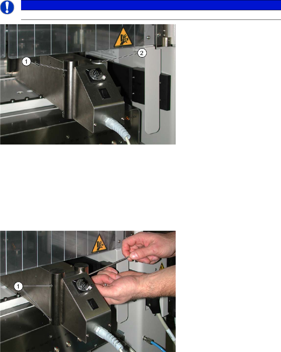
5.4 Hand Guards
The DIP module is set up like a feeder on the changeover table. As with a feeder, the DIP module needs
to be protected above to prevent unauthorized access. To achieve this, one of two hand guards - the
specific version depends on the machine type - must be fitted on the DIP module.
As a default, the DIP module is supplied with the high hand guard and can therefore be set up in all
SIPLACE placement machines except D1/D2.
The short hand guard supports supplied need to be used instead of the high ones when working with
D1/D2 machines.
To change the hand guards, proceed as follows:
►Loosen the two screws attached to both sides of the DIP module (1).
►Remove the hand guard.
►Fit the other hand guard on both sides of the DIP module.
NOTICE
Observe the warnings on the DIP module.
Legend:
1 High hand guard – for all SIPLACE placement machines except D1 /D2
2 Low hand guard – for D1/D2 SIPLACE placement machines

Dip Module
Additional Spacer (Optional)
78 User Manual SIPLACE S-Feeder
5.5 Additional Spacer (Optional)
The following spacer set is available for version -03 of the DIP module:
Spacer set 125 µm - 400 µm (Item No.: 00378544-xx).
The spacers sizes are available in 25 µm steps:
125 µm / 150 µm / 175 µm / 200 µm / 225 µm / 250 µm /
275 µm / 300 µm / 325 µm / 350 µm / 375 µm / 400 µm
The special spacers can be used up to a thickness of 400µ (in steps of 25µ).
The reason for this is, that when using the 275µ spacer, for example, only a measured layer thickness
of 175µ - 200µ is reached. The specified value on the spacers is therefore not the generated layer thick-
ness but only the gap between the rotary plate and the squeegee.
When using the 25µ to 75µ spacers, this effect is not quite as prominent and can therefore be ignored.
The higher the layer thickness is, the greater the difference will be between the gap and the actual layer
created.
The actual layer thickness needs to be determined by measuring the layer thickness. To do this, use the
layer thickness comb mentioned below.
5.6 Layer Thickness Comb
To check the layer thickness, we recommend using the layer thickness measuring comb shown here.
This comb can be ordered from:
Zehntner GmbH
Testing Instruments
Gewerbestrasse 4
CH - 4450 Sissach
Switzerland
Tel.: +41 (0)61 953 05 50
Fax: +41 (0)61 953 05 51
www.zehntner.com
zehntner@zehntner.com