00196376-0102_UM S-Feeder_EN.pdf - 第79页
Dip Module Refill Recommendations User Manual SIPLACE S-Feeder 79 5.7 Refill Recommendations The following diagram shows a 3 m l filling level with a 25 µm spa cer. Legend: 1 Critical minimum amount 2 Minimum amount 3 Co…

Dip Module
Additional Spacer (Optional)
78 User Manual SIPLACE S-Feeder
5.5 Additional Spacer (Optional)
The following spacer set is available for version -03 of the DIP module:
Spacer set 125 µm - 400 µm (Item No.: 00378544-xx).
The spacers sizes are available in 25 µm steps:
125 µm / 150 µm / 175 µm / 200 µm / 225 µm / 250 µm /
275 µm / 300 µm / 325 µm / 350 µm / 375 µm / 400 µm
The special spacers can be used up to a thickness of 400µ (in steps of 25µ).
The reason for this is, that when using the 275µ spacer, for example, only a measured layer thickness
of 175µ - 200µ is reached. The specified value on the spacers is therefore not the generated layer thick-
ness but only the gap between the rotary plate and the squeegee.
When using the 25µ to 75µ spacers, this effect is not quite as prominent and can therefore be ignored.
The higher the layer thickness is, the greater the difference will be between the gap and the actual layer
created.
The actual layer thickness needs to be determined by measuring the layer thickness. To do this, use the
layer thickness comb mentioned below.
5.6 Layer Thickness Comb
To check the layer thickness, we recommend using the layer thickness measuring comb shown here.
This comb can be ordered from:
Zehntner GmbH
Testing Instruments
Gewerbestrasse 4
CH - 4450 Sissach
Switzerland
Tel.: +41 (0)61 953 05 50
Fax: +41 (0)61 953 05 51
www.zehntner.com
zehntner@zehntner.com
Dip Module
Refill Recommendations
User Manual SIPLACE S-Feeder 79
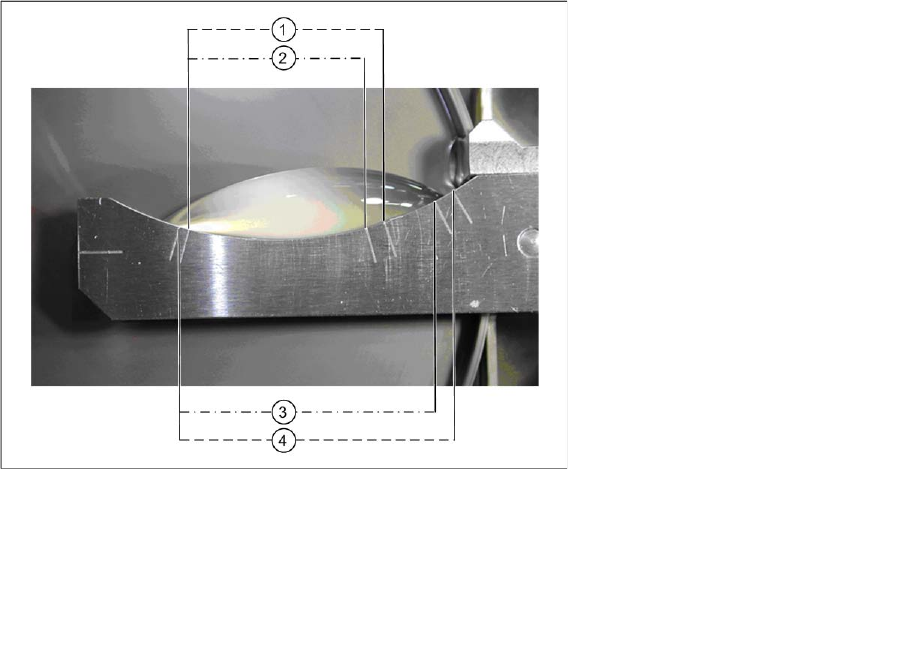
5.7 Refill Recommendations
The following diagram shows a 3 ml filling level with a 25 µm spacer.
Legend:
1 Critical minimum amount
2 Minimum amount
3 Correct amount
4 Maximum amount
Dip Module
Software Version 5xx / 6xx (Platform 2) Restrictions
80 User Manual SIPLACE S-Feeder
5.8 Software Version 5xx / 6xx (Platform 2)
5.8.1 Restrictions
▪ The placement performance of the machine is limited by the DIP module.
▪ Only DIP modules with circular plates are supported.
▪ The DIP module itself (HW) does not report any errors (non-intelligent feeder) i.e. the software is
unable to determine whether a DIP module is connected or whether the rotary movement of the plate
was successful or not.
▪ When dipping components, no placement data is generated for user information (OIS).
▪ The use of feeder cover plates is not possible with DIP modules.
▪ Dipping can be performed with the Twin head, 6 segment and 12 segment C&P heads.
▪ A gantry can only be operated with one DIP module (even when pickup can be performed from two
locations).
▪ The DIP module can only be set up on S tables.
5.8.2 Module Function
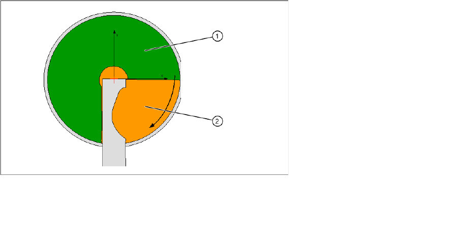
5.8.2.1 DIP area
The whole diameter of the plate is not available for dipping. This is partially restricted by the squeegee.
In addition, dipping may not be performed directly next to the squeegee for technical reasons, causing
excess medium to collect in 4 areas (on the bottom right of the DIP plate).
Dipping area on a module
In HF series / X series / and D series machines, locations 1 and 3 only have a dipping area of 180°in the
front part of the DIP module.
▪ The module can be set up at all locations.
From SIPLACE Pro 3.2, up to three modules can be set up per placement machine.
▪ C&P6 and C&P12 placement heads work according to the "Dipping before Vision" principle. When
using the Twin head, "Vision before dipping" is also possible.
▪ The number of DIP cycles before the DIP plate is rotated and the components are placed is auto-
matically determined by the station, depending on the component sizes.
Legend:
1 DIP area
2 Refill area