00196376-0102_UM S-Feeder_EN.pdf - 第80页
Dip M odule Software Version 5xx / 6xx (Platform 2) Restrictions 80 User Manual SIPLACE S-Feeder 5.8 Software Version 5xx / 6xx (Platform 2) 5.8.1 Restrictions ▪ The plac ement per form ance of the machine i s limited by…
Dip Module
Refill Recommendations
User Manual SIPLACE S-Feeder 79
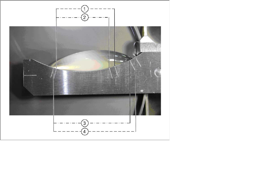
5.7 Refill Recommendations
The following diagram shows a 3 ml filling level with a 25 µm spacer.
Legend:
1 Critical minimum amount
2 Minimum amount
3 Correct amount
4 Maximum amount
Dip Module
Software Version 5xx / 6xx (Platform 2) Restrictions
80 User Manual SIPLACE S-Feeder
5.8 Software Version 5xx / 6xx (Platform 2)
5.8.1 Restrictions
▪ The placement performance of the machine is limited by the DIP module.
▪ Only DIP modules with circular plates are supported.
▪ The DIP module itself (HW) does not report any errors (non-intelligent feeder) i.e. the software is
unable to determine whether a DIP module is connected or whether the rotary movement of the plate
was successful or not.
▪ When dipping components, no placement data is generated for user information (OIS).
▪ The use of feeder cover plates is not possible with DIP modules.
▪ Dipping can be performed with the Twin head, 6 segment and 12 segment C&P heads.
▪ A gantry can only be operated with one DIP module (even when pickup can be performed from two
locations).
▪ The DIP module can only be set up on S tables.
5.8.2 Module Function
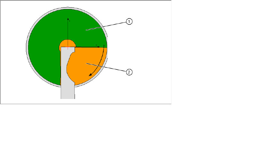
5.8.2.1 DIP area
The whole diameter of the plate is not available for dipping. This is partially restricted by the squeegee.
In addition, dipping may not be performed directly next to the squeegee for technical reasons, causing
excess medium to collect in 4 areas (on the bottom right of the DIP plate).
Dipping area on a module
In HF series / X series / and D series machines, locations 1 and 3 only have a dipping area of 180°in the
front part of the DIP module.
▪ The module can be set up at all locations.
From SIPLACE Pro 3.2, up to three modules can be set up per placement machine.
▪ C&P6 and C&P12 placement heads work according to the "Dipping before Vision" principle. When
using the Twin head, "Vision before dipping" is also possible.
▪ The number of DIP cycles before the DIP plate is rotated and the components are placed is auto-
matically determined by the station, depending on the component sizes.
Legend:
1 DIP area
2 Refill area
Dip Module
Integration in the Overall System Software Version 5xx / 6xx (Platform 2)
User Manual SIPLACE S-Feeder 81
▪ Every 10 minutes, at the latest, the DIP plate rotates and circulates the layer of dipping medium, to
keep the surface fluid.
When the setup is defined, this immediately triggers rotation of the DIP plate.
▪ In the event of an error, the function "Bringing into service" is enabled by the station software.
This triggers a rotation of the DIP plate so that the dipping medium is circulated.
5.8.2.2 Dipping Sequence
▪ Component presence test via vacuum check, component present before dipping?
▪ Positioning downwards with DIP force
▪ Programmed holding time, which keeps the component in the medium (dwell time)
▪ Positioning upwards with slow start, to ensure that the component is not lost in the flux.
▪ Component presence test via vacuum check, to ensure that the component was not lost in the flux.
5.8.3 Integration in the Overall System
SIPLACE Pro
Component Editor:
components can be marked for dipping in the Component Editor.
Component Shape Editor:
The dipping mode can be programmed in the Component Shape Editor, as can various dipping
parameters, such as the order of Vision/dipping and the dipping dwell time.
Setup:
When using several DIP modules, different layer heights and materials can be used. The programmer
must make sure that the required components are in the same location as the DIP module.
The DIP module is set up like a conventional feeder on a changeover table.
Station computer
The GUI provides the following user interfaces which are relevant for the DIP module:
▪ New view for displaying and operating all DIP modules
▪ Advanced view for teaching and measuring component shapes
▪ Advanced view for omitting components
▪ Advanced view "Software Options" for switching dipping and the DIP module on and off
▪ Error messages relating to the DIP module in the error line and in the "Error display" view
Hardware
The layer height is set at the DIP module with the help of a metal disk. Typically, the layer height should
be set to 40 - 50% of the BGA ball radius. The medium is applied manually by the operator. The DIP
module has a lockable potentiometer for setting the rotation speed and a button for starting plate rotation.