00196376-0102_UM S-Feeder_EN.pdf - 第84页
Dip M odule Software Version 4xx (Platform 1) Integration in the Overall System 84 User Manual SIPLACE S-Feeder 5.9.3 Integration in the Overall System SIPLACE Pro Component Editor : Entries in the Component Editor are n…
Dip Module
Restrictions Software Version 4xx (Platform 1)
User Manual SIPLACE S-Feeder 83
5.9 Software Version 4xx (Platform 1)
5.9.1 Restrictions
The placement performance of the machine is limited by the DIP module.
Only DIP modules with circular plates are supported.
The DIP module itself (HW) does not report any errors (non-intelligent feeder) i.e. the software is unable
to determine whether a DIP module is connected or whether the rotary movement of the plate was
successful or not.
When dipping components, no placement data is generated for user information (OIS and MaDaMaS).
The use of feeder cover plates is not possible with DIP modules.
Dipping is possible
▪ With the P&P placement head (with all SW versions)
▪ With a C&P 6 head on a gantry (with all SW versions).
▪ With a C&P 12 head on a gantry (from SW version 408).
Only one DIP module can be used per placement machine.
5.9.2 Module Function
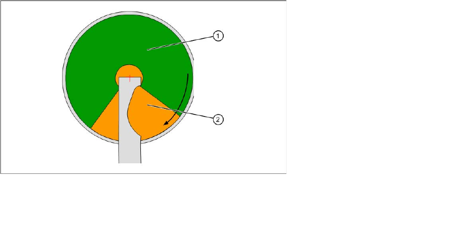
The whole diameter of the plate is not available for dipping. This is partially restricted by the squeegee.
In addition, dipping may not be performed directly next to the squeegee for technical reasons, causing
excess medium to collect in 4 areas (on the bottom right of the DIP plate).
For these reasons, the area available for dipping is defined via the parameters R1, R2, Phi1 and Ph2.
Dipping area on a module
▪ The DIP module can be set up at all locations.
▪ C&P6 and C&P 12 (408 only) placement heads work according to the "Dipping before Vision"
principle. When using the P&P head, "Vision before dipping" is also possible.
▪ The DIP position is a fixed setting on the rotary plate.
Legend:
1 DIP area
2 Refill area
Dip Module
Software Version 4xx (Platform 1) Integration in the Overall System
84 User Manual SIPLACE S-Feeder
5.9.3 Integration in the Overall System
SIPLACE Pro
Component Editor:
Entries in the Component Editor are not transmitted to the station with software version 4xx.
Component Shape Editor:
Entries in the Component Shape Editor are not transmitted to the station with software version 4xx.
Setup:
Only one DIP module can be set up per placement machine.
▪ In station software versions up to 407 the programmer must keep the location (18 tracks) manually
free for a DIP module.
▪ From station software versions 408 (SIPLACE Pro 3.2) the DIP module can be programmed on a
specific table, to ensure that this location is not blocked by other feeders.
Station computer
The GUI provides the following user interfaces which are relevant for the DIP module:
▪ New display view, programming and operation of the DIP module
▪ Error messages relating to the DIP module in the error line and in the "Error display" view
Hardware
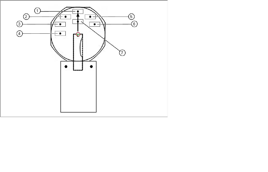
The layer height is set at the DIP module with the help of a metal disk. The medium is applied manually
be the operator. The DIP module has a lockable potentiometer for setting the rotation speed and a button
for starting plate rotation.
Legend:
1 Position S1 5 Position S5
2 Position S2 6 Position S6
3 Position S3 7 Position IC
4 Position S4
Dip Module
Configuring the DIP Module Software Version 4xx (Platform 1)
User Manual SIPLACE S-Feeder 85
5.9.4 Configuring the DIP Module
The DIP module is only configured on the station computer. The following data is required:
Location and track: only one DIP module can be set up per machine.
The possible location is from track 7 to 111 (inclusive), whereby the specified track must correspond to
the electrical connection and be in the center of the module.
Coordinates for plate center in the machine coordinate system (X direction is PCB direction of transport,
Y direction is vertical to this and to the left, positive).
Z position of plate base. The zero point is the upper edge of the input conveyor, higher (positive) values
progress upwards. The plate base is lower than the conveyor, meaning that negative values need to be
entered.
5.9.4.1 Recording the X/Y Position
►Start SITEST from V 404.01.
►Determine the X and Y coordinates by moving the DIP module in SITEST.
Use the "LP-Kamera teachen" function to establish the X/Y coordinates in SITEST.
►To do this, position the camera on the center of the rotary plate. Make a note of the values so that
they can be entered in the station software.
NOTICE
Default = 0: with safety buffer of approx. 4000 mm
If the default value of 0 is kept, the path of 4000 mm will be travelled in slow Z axis mode. This
leads to minor loss of performance.
CAUTION
Type and source of the danger
SITEST may only be implemented by persons who have been trained to do so by ASM
Assembly Systems and who are therefore authorized to use the program.
NOTICE
Type and source of the danger
There are no single functions and SITEST functions available for the DIP module.