00196376-0102_UM S-Feeder_EN.pdf - 第89页
Dip Module Data Input at Station Computer Software Version 4 xx (Platform 1) User Manual SIPLACE S-Feeder 89 The following data nee ds to be entered: CS Number : The component shape nu mber for the respective component A…
Dip Module
Software Version 4xx (Platform 1) Data Input at Station Computer
88 User Manual SIPLACE S-Feeder
5.9.6 Data Input at Station Computer
5.9.6.1 Editing the Component Shape List
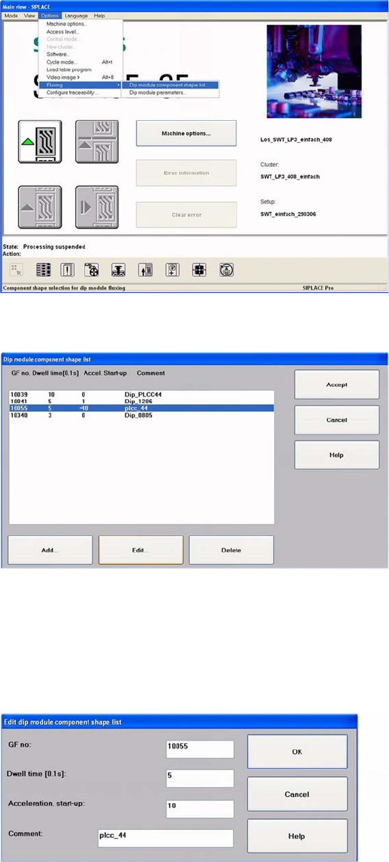
►Select:
"Options" -> "Fluxing" -> "Dip module CS list" from the menu.
User interface - selecting the component shape list for the DIP procedure
The DIP module component shape list will be shown.
DIP module - component shape list
►To add a new component, click on the "Add" button.
The following screen will be shown.
►To edit an existing or new component, mark the line concerned.
►Click on the Edit button, to edit an existing component shape.
The following dialog box will be shown.
DIP module component shape list: entering the "DIP module parameters"
Dip Module
Data Input at Station Computer Software Version 4xx (Platform 1)
User Manual SIPLACE S-Feeder 89
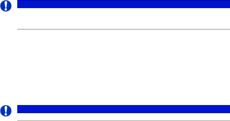
The following data needs to be entered:
CS Number:
The component shape number for the respective component
A component shape number between 1 and 32767 can be entered.
Dwell Time:
The time that the component is held on the board, in 1/10 seconds.
Values of 0 to 30 possible, for 0-3 s (typical: "10" for 1 sec.).
Acceleration for upwards travel
When the value is 0, the preset values from the line computer are used.
In this case, the Z axis moves up with the same acceleration used for lowering (downwards travel).
Enter a different value (other than 0) if you require slower upwards travel than that preset by the line
computer or SIPLACE Pro computer.
Valid values are those between 1 and 100.
When the value is not 0, the Z axis will move upwards from the DIP module plate with the specified per-
centage of the maximum Z axis acceleration.
Comments
You can enter a comment about the component concerned (e.g. PLCC).
Confirm you entry with OK.
Save the edited component shape list with Accept.
NOTICE
A change in the acceleration can be necessary, for example, if the component remains stuck
to the plate after dipping - as a result of low flux/conductive adhesive viscosity. a reduction in
the speed of upwards movement has a negative influence on placement performance.
NOTICE
Up to 25 component shapes can be entered for dipping in the station computer.
Dip Module
Software Version 4xx (Platform 1) Data Input at Station Computer
90 User Manual SIPLACE S-Feeder
5.9.6.2 Editing the DIP Module Parameters
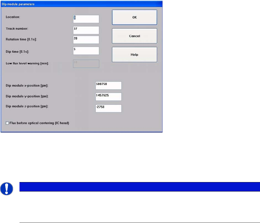
►Select:
"Options" -> "Fluxing" -> "DIP module parameters" from the menu to specify data for the DIP module
and for the superior process sequence.
Screen for entering the DIP module parameters
►Set the location (1-4) and the track number (7-111) of the table at which the DIP module is set up
and connected.
the track specified here must correspond with the center of the module axis along the length.
Tracks 7 and 111 are the outermost tracks in which the module can be set up.
►Set the following parameters:
Turning Time:
Ensures that a complete revolution can be performed with the set speed (typical: 30 and a speed of '4').
Dipping Time:
Defines the dwell time which the components are kept in the DIP medium, to ensure that they are com-
pletely coated.
DIP-Module X-position / DIP-Module Y-position:
These are the coordinates for the DIP plate rotary axis, determined in SITEST with the component
camera. The DIP positions for the placement head or segments are determined form here.
DIP-Module Z-position:
This is the target height for the Z axis, to ensure that the DIP procedure can be performed rapidly and
with care. Components with the same component shape can have a difference in height of up to 4 mm
and the dipping procedure will still be performed correctly.
NOTICE
The data entered at the track number is only required for powering the module electrically. The
setup location must be specified explicitly (x/Y/Z position) in this menu. As the DIP module - like
all feeders - needs to be connected to the appropriate socket on the changeover table connec-
tion panel, the setup track and the track for the electrical connection are identical.