CM88Maintenace2x.PDF - 第44页
Page 3-16 3Y3C-E-MMD03-A02-02 Check and Solutions 2. Checking the shielding timing of sensor to be changed Display the “No. 28 32 mm tape feed Permission,” “No. 27 T ape feed Permission,” “No. 33 Pickup Permission,” and …
Page 3-15
SOLUTIONS FOR ERROR
3
3Y3C-E-MMD03-A02-00
Check and Solutions
3-2-9 Production End Signal Detected
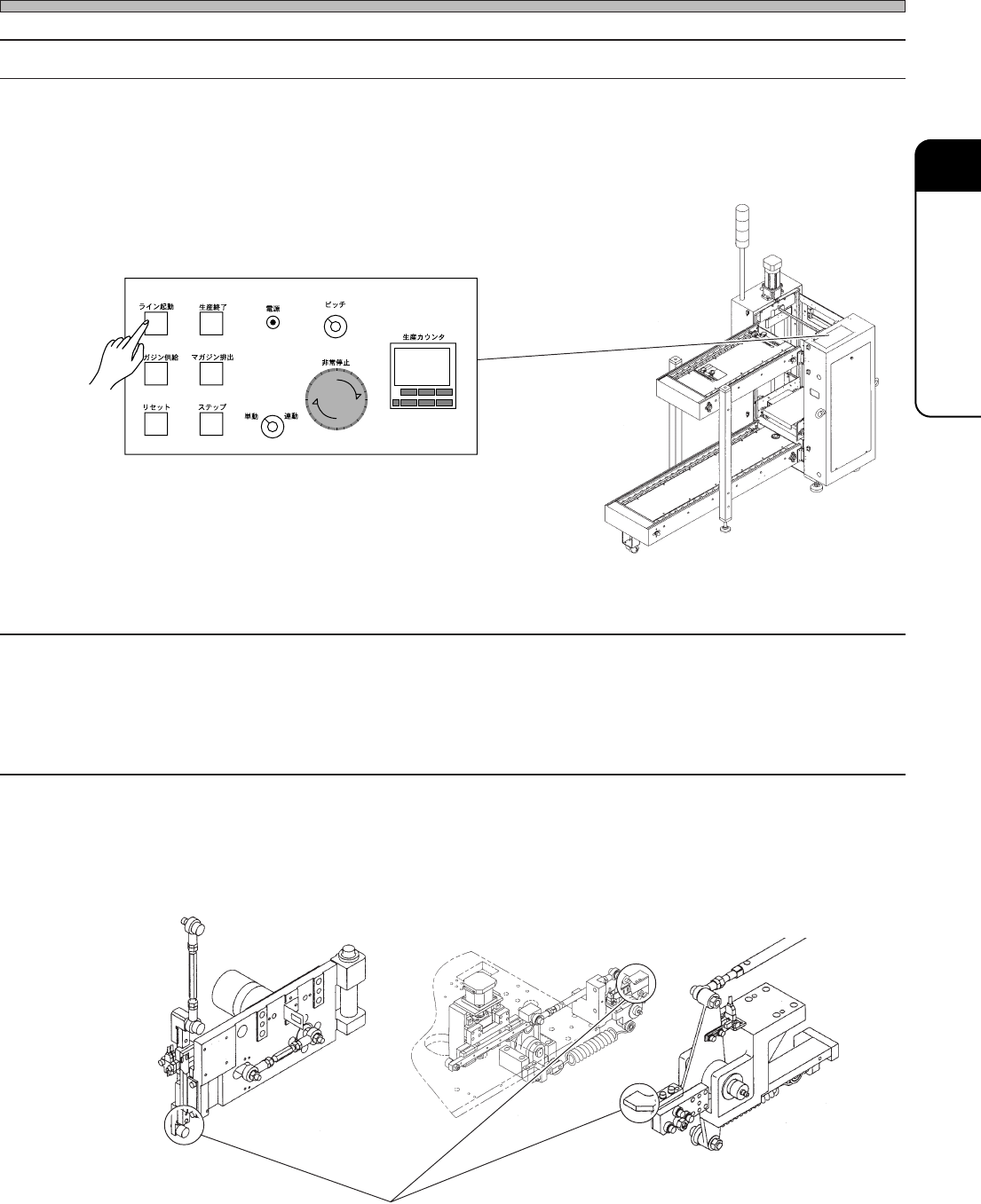
1. Canceling the production end signal
As the production end signal is output from the front stocker of slotted magazine loader or stacking
magazine loader, press the LINE START switch to cancel the production end signal.
3-2-10
Adhesive Tape Feed Rod Descend (Adhesive Tape Feed Interlock)
Tape Feed Rod Descend (Adhesive Tape Feed Interlock)
Pickup Pos Head Descend (Pickup Head Interlock)
Mount Pos Head Descend (Mount Head Interlock)
1. Checking the state of cam follower (or Rod end)
Move up and down the part circled in the lower figure by hand, and check the wear and damage. If
wear or damage is found, make contact with us for changing.
Upper operation panel
LINE
START
PROD.
END
PUT IN
MAGAZINE
RESET
STEP
TAKE OUT
MAGAZINE
POWER
MANU.
PITCH
EMERGENCY
PRODUCTION
COUNTER
R
S
E
T
E
R
S
E
T
E
1
23
4
AUTO
033C-PS006
Check position for the wear and damage.
01DTC2AB
01DPC2AA
01DQC1AA
Page 3-16
3Y3C-E-MMD03-A02-02
Check and Solutions
2. Checking the shielding timing of sensor to be changed
Display the “No. 28 32 mm tape feed Permission,” “No. 27 Tape feed Permission,” “No. 33 Pickup
Permission,” and “No. 37 Mount Permission” on the “Output check (address)” screen after “Ma-
chine adjust” by the error display.
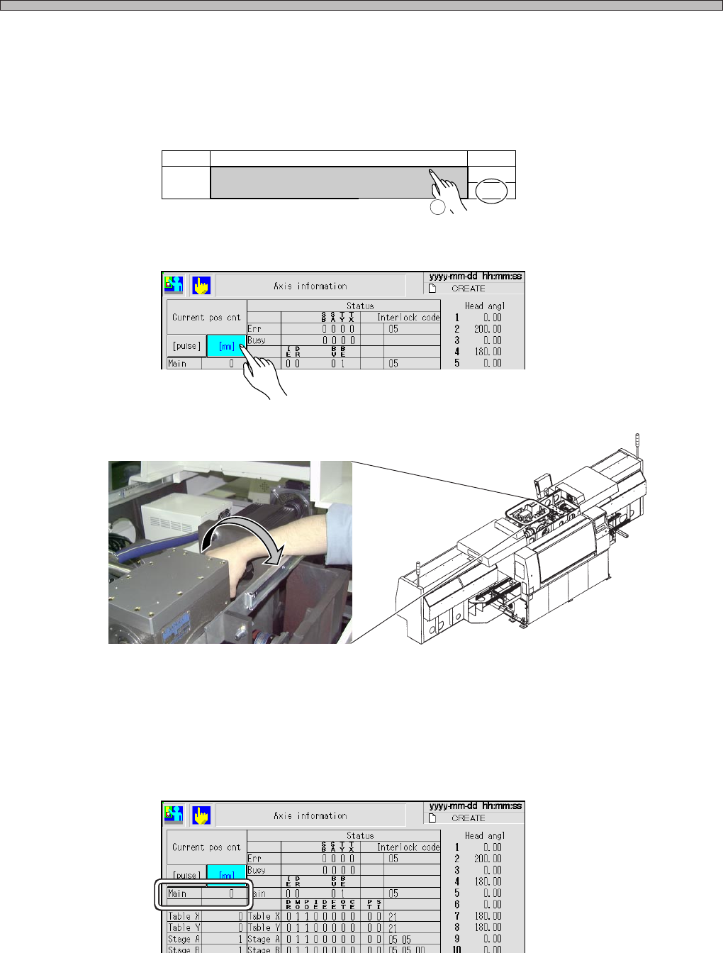
1.Press the name part to make the output value ON. The moving part stopper retracts, and it gets
the movement permission state.
2.Display the “Axis information” screen after “Machine adjust,” and press the [mm] switch of the
current position counter.
3.Rotate the coupling of main motor by hand until the dog shields (LED lighting) the moving part
sensor displayed as the error, and stop it when it shields the sensor (LED lights).
4.Check the value of “Main” on the “Axis info” screen at the position where the sensor is shielded
(LED lights).
If the proper cam angle (value of “Main”) is not checked after carrying out procedures 1 to 4, the
sensor (dog) position may be deviated or the timing belt may be loosened. Make contact with us for
the adjustment.
No. Name Bit
Tape feed Permission
27
0
ON
Operation
1
PH230 (Adhesive tape feed interlock) :199° ± 2°
PH231 (Tape feed interlock ) :284° ± 2°
PH232 (Pickup upper limit) :285° ± 2°
PH263 (Mount upper limit) :279° ± 2°
3Y3C-042P
3Y3C-AD01
3Y3C-EEn-MaAi-007
3Y3C-EEn-MaAi-007
Page 3-17
SOLUTIONS FOR ERROR
3
3Y3C-E-MMD03-A02-01
Check and Solutions
3Y3C-AI01
3Y3C-011P
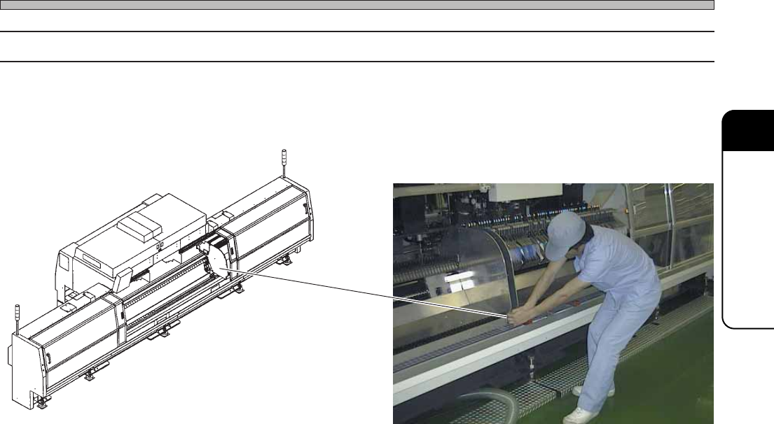
3-2-11 Stage Interlock (Stage Interference)
1. Removing the stage
If the stage is extremely near to the other one, hold the lower part of squeegee and remove the one
by 5 cm to 10 cm as shown in the picture below.