CM88Maintenace2x.PDF - 第45页
Page 3-17 SOLUTIONS FOR ERROR 3 3Y3C-E-MMD03-A02-01 Check and Solutions 3Y3C-AI01 3Y3C-01 1P 3-2-1 1 Stage Interlock (Stage Interference) 1. Removing the stage If the stage is extremely near to the other one, hold the lo…
Page 3-16
3Y3C-E-MMD03-A02-02
Check and Solutions
2. Checking the shielding timing of sensor to be changed
Display the “No. 28 32 mm tape feed Permission,” “No. 27 Tape feed Permission,” “No. 33 Pickup
Permission,” and “No. 37 Mount Permission” on the “Output check (address)” screen after “Ma-
chine adjust” by the error display.
1.Press the name part to make the output value ON. The moving part stopper retracts, and it gets
the movement permission state.
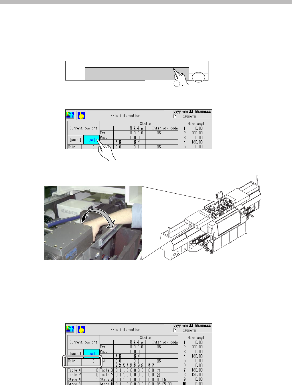
2.Display the “Axis information” screen after “Machine adjust,” and press the [mm] switch of the
current position counter.
3.Rotate the coupling of main motor by hand until the dog shields (LED lighting) the moving part
sensor displayed as the error, and stop it when it shields the sensor (LED lights).
4.Check the value of “Main” on the “Axis info” screen at the position where the sensor is shielded
(LED lights).
If the proper cam angle (value of “Main”) is not checked after carrying out procedures 1 to 4, the
sensor (dog) position may be deviated or the timing belt may be loosened. Make contact with us for
the adjustment.
No. Name Bit
Tape feed Permission
27
0
ON
Operation
1
PH230 (Adhesive tape feed interlock) :199° ± 2°
PH231 (Tape feed interlock ) :284° ± 2°
PH232 (Pickup upper limit) :285° ± 2°
PH263 (Mount upper limit) :279° ± 2°
3Y3C-042P
3Y3C-AD01
3Y3C-EEn-MaAi-007
3Y3C-EEn-MaAi-007
Page 3-17
SOLUTIONS FOR ERROR
3
3Y3C-E-MMD03-A02-01
Check and Solutions
3Y3C-AI01
3Y3C-011P
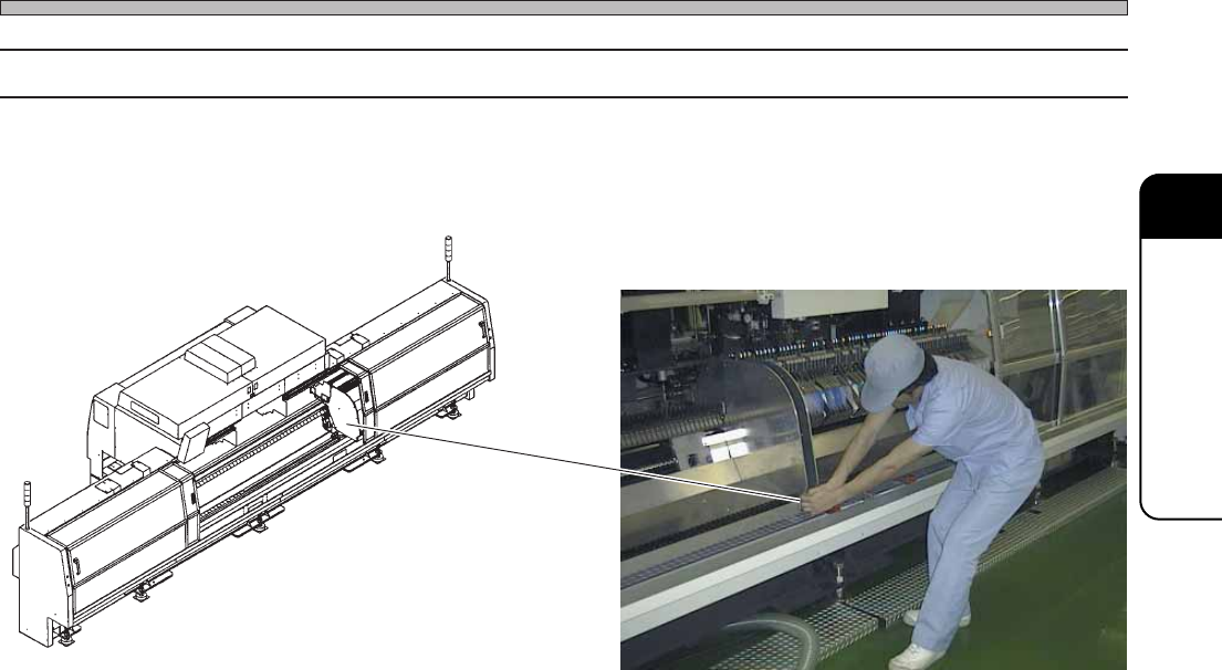
3-2-11 Stage Interlock (Stage Interference)
1. Removing the stage
If the stage is extremely near to the other one, hold the lower part of squeegee and remove the one
by 5 cm to 10 cm as shown in the picture below.
Page 3-18
3Y3C-E-MMD03-A02-01
Check and Solutions
3-2-12 Blower Over Heat
Vacuum Pump Over Heat
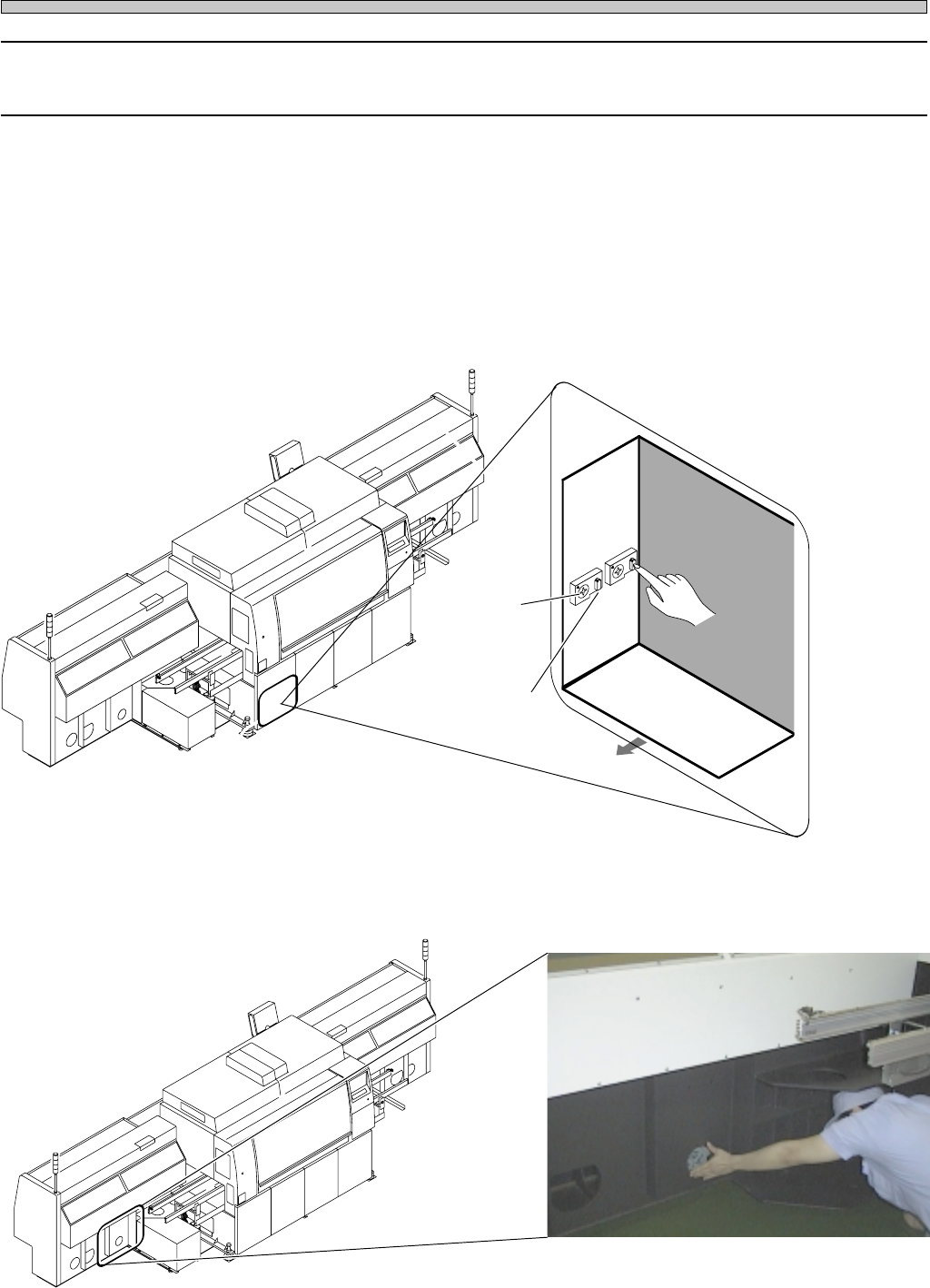
1. Setting the current protection value
Check that the current protection setting value of thermal relay which is at the left side in the cover
is 4.2 A (60Hz) or 3.0 A (50Hz) for the blower, and 2.4 A for the vacuum pump.
If settings are wrong, set them to the value above.
∗ Cancel the tripped thermal relay.
Note) Make sure of doing after solutions for error (1 and 2).
Press the reset switch of thermal switch at the left side in the cover.
2. Checking the movement of cooling fan
If the wind is not sent from the wind opening to the outside, it may be the trouble of cooling fan.
Make contact with us for changing them.
3Y3C-095P
4G3C-AA01
4G3C-AA01
Right : Thermal relay for blower
Left : Thermal relay for vacuum pump
Current
protection
value
Left side in
the cover
Reset switch
POWER BOX
Forward
3Y3C-113E