CM88Maintenace2x.PDF - 第59页
Page 3-31 SOLUTIONS FOR ERROR 3 3Y3C-E-MMD03-A03-02 Check and Solutions 3-2-27 Head Theta T ime Out Error Head Theta No Response Err Head Theta Communication Error Head Theta Motion Incomplete Head Theta is Bad Head Head…
Page 3-30
3Y3C-E-MMD03-A03-01
Check and Solutions
3-2-26 Chip Send Select Partial
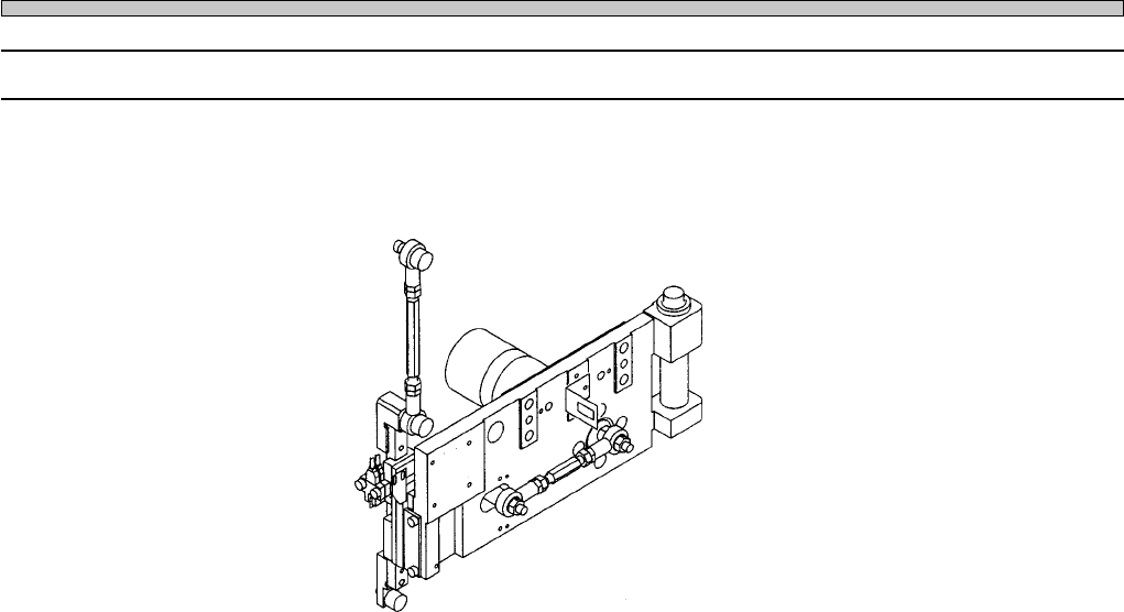
1. Cleaning the moving part
Check for the clogging of tape feeder. If clogging of dust is found, clean it.
2. Connecting connectors
Check the connection of connectors for the tape feeder, and recover the proper state if the connec-
tion of connectors has a trouble.
01DTC2AB
Tape feeder
Page 3-31
SOLUTIONS FOR ERROR
3
3Y3C-E-MMD03-A03-02
Check and Solutions
3-2-27 Head Theta Time Out Error
Head Theta No Response Err
Head Theta Communication Error
Head Theta Motion Incomplete
Head Theta is Bad Head
Head Theta Origin Motion Incomplete
Head Theta Data Read Error
Head Theta Controller Error
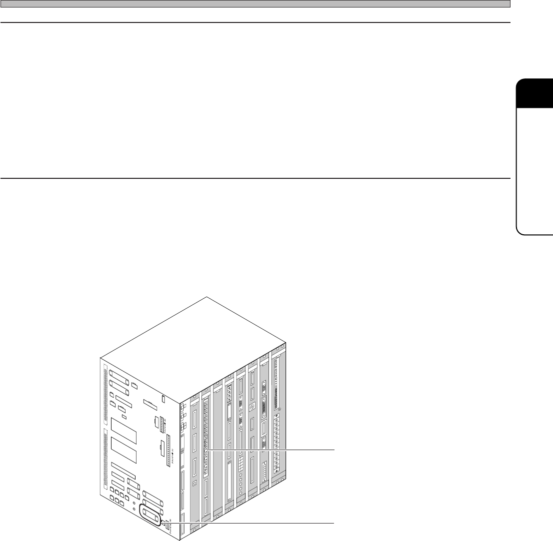
1. Connecting connectors
Check the state of CPU box side connector (CN18), and recover it if necessary.
2. Checking the state of board (NFM0CL)
If wrong setting is found, set it properly.
Board (NFM0CL)
Connector (CN18)
C
N
0
1
C
N
2
5
C
N
0
0
C
N
1
3
C
N
2
0
C
N
5
1
C
N
2
7
C
N
5
S
W
1
C
N
4
C
N
1
9
C
N
2
3
C
N
2
4
C
N
5
0
C
N
2
6
C
N
1
4
C
N
2
8
C
N
2
9
C
N
3
0
C
N
3
1
C
N
3
2
C
N
3
3
C
N
3
4
N
R
1
N
R
2
C
N
1
8
C
N
8
C
N
7
C
N
T
E
S
T
3
C
N
T
E
S
T
4
CNTEST 1
CNTEST 2
CN2
CN1
CN21
CN22CN17
CN11
CN12
CN9
CN10
CN15
CN1
CN2
CN3
OPT1OPT2OPT3OPT4OPT5
OPT6OPT7
CN1
CN2
CN3
CN1
CN2
CN3
CN4
CN4
CN2
CN1
CN3
CN5
CN
10
CN
9
CN
7
CN
6
CN1CN2
CN3
CN4
CN5
CN6
CN2
CN3
CN4
CN5
CN
8
NC
GND1
12V
GND2
GND1
+5V
+24V
-12V
+12V
+5V
GND3
+24V
-12V
+12V
G
N
D
2
G
N
D
1
+5VC
NC
GND3
+24V
-12V
GND2
+12V
G
ND1
+5V
NC
L
N
FG
E
C
5
5
C
A
N
F
M
0
C
K
C
M
M
7
C
A
M
C
M
A
E
R
P
R
M
7E
Q
E
L
L
Z
E
A
S
C
M
W
E
E
P
U
0
2
E
1
GND
+5V
NC
G
ND1
G
ND
+5V
3Y3C-109E
∗ The description is for the CPU BOX for CM88S-M.
Page 3-32
3Y3C-E-MMD03-A03-02
Check and Solutions
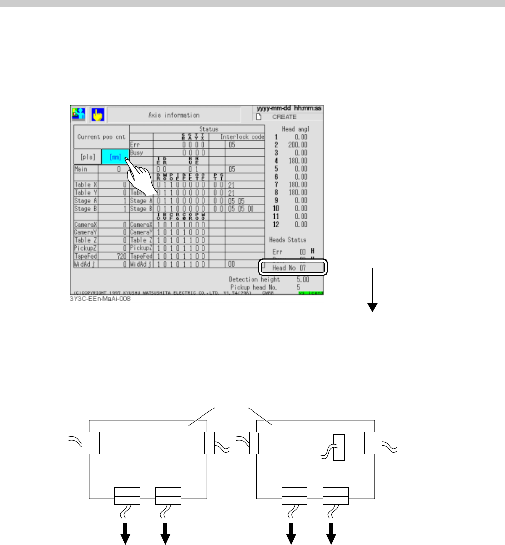
3. Checking the state of theta-axis board
1.Check “Head No. ∗ ∗ ” displayed at the lower right on the “Axis information” screen after “Machine
adjust.”
(See “Stop history in 5-2 Stop information” in Operating Manual (for Operators), for checking the
state.)
The head of No. ∗ ∗ is the one with error
2.Check the connection on the upper theta axis board connector with covers removed. If a loose
connector is found, connect it properly, and reset the cover.
3Y3C-117E
θ-axis board
Head Head Head Head
×5
×1
E.g.) For number 7 head, it is described “Head No. 07”