CM88Maintenace2x.PDF - 第64页
Page 3-36 Check and Solutions 3Y3C-E-MMD03-A03-01 3-2-32 Disconnection Fiber Line 1. Setting and Connecting the board (NFM0CL) If wrong connection of CPU box front side board (NFM0CL) is found, connect it properly . If i…
Page 3-35
SOLUTIONS FOR ERROR
3
Check and Solutions
3Y3C-E-MMD03-A03-01
3-2-30 Data Error
1. Power OFF to Power ON
If the trouble is not recovered after restarting up the power, make contact with us.
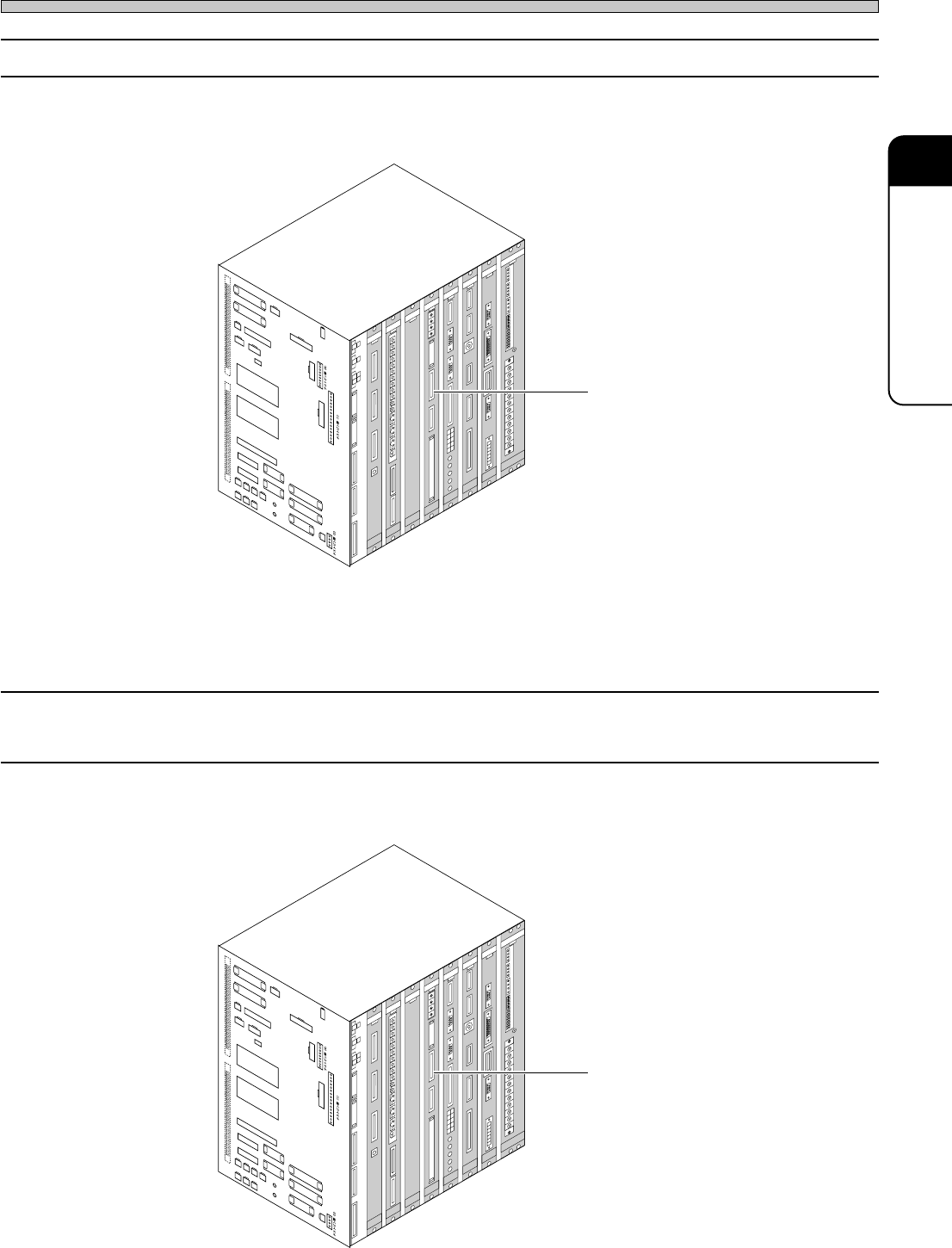
2. Setting and connecting the board (MCMAER)
If disconnection or wrong setting of CPU box front side board (MCMAER) is found, connect and set
them properly.
3-2-31 (+) Overrun
(–) Overrun
1. Setting and connecting the board (MCMAER)
If disconnection or wrong setting of CPU box front side board (MCMAER) is found, connect and set
them properly.
Board (MCMAER)
CN01
CN25
CN00
CN13
CN20
CN51
CN27
CN5
SW1
CN4
CN19
CN23
CN24
CN50
CN26
CN14
CN28
CN29
CN30
CN31
CN32
CN33
CN34
NR1
NR2
CN18
CN8
CN7
CN
TEST 3
CNTEST 4
CNTEST 1
CNTEST 2
CN2
CN1
CN21
CN22CN17
CN11
CN12
CN9
CN10
CN15
CN1
CN2
CN3
OPT1OPT2OPT3OPT4OPT5
OPT6OPT7
CN1
CN2
CN3
CN1
CN2
CN3
CN4
CN4
CN2
CN1
CN3
CN5
CN
10
CN
9
CN
7
CN
6
CN1CN2
CN3
CN4
CN5
CN6
CN2
CN3
CN4
CN5
CN
8
NC
GND1
12V
GND2
GND1
+5V
+24V
-12V
+12V
+5V
GND3
+24V
-12V
+12V
GND2
GND1
+5VC
NC
GND3
+24V
-12V
GND2
+12V
GND1
+5V
NC
L
N
FG
EC55CA
NFM0CK CMM7CA
MCMAER
PRM7EQ
ELLZEA
SCMWEE
PU02E1
GND
+5V
NC
GND1
GND
+5V
3Y3C-109E
∗ The description is for the CPU BOX for CM88S-M.
∗ The description is for the CPU BOX for CM88S-M.
Page 3-36
Check and Solutions
3Y3C-E-MMD03-A03-01
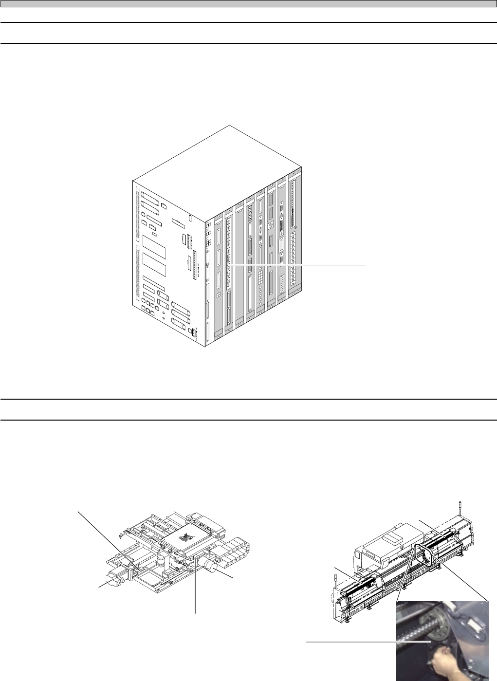
3-2-32 Disconnection Fiber Line
1. Setting and Connecting the board (NFM0CL)
If wrong connection of CPU box front side board (NFM0CL) is found, connect it properly. If it is not
found, the optical fiber cable may be disconnected. Make contact with us for changing.
3-2-33 Time Over Fault
1. Checking the state of error axis
If the looseness of the motor coupling or timing belt is found, make contact with us for adjusting.
Board (NFM0CL)
CN01
CN25
CN00
CN13
CN20
CN51
CN27
CN5
SW1
CN4
CN19
CN23
CN24
CN50
CN26
CN14
CN28
CN29
CN30
CN31
CN32
CN33
CN34
NR1
NR2
CN18
CN8
CN7
CN
TEST 3
CNTEST 4
CNTEST 1
CNTEST 2
CN2
CN1
CN21
CN22CN17
CN11
CN12
CN9
CN10
CN15
CN1
CN2
CN3
OPT1OPT2OPT3OPT4OPT5
OPT6OPT7
CN1
CN2
CN3
CN1
CN2
CN3
CN4
CN4
CN2
CN1
CN3
CN5
CN
10
CN
9
CN
7
CN
6
CN1CN2
CN3
CN4
CN5
CN6
CN2
CN3
CN4
CN5
CN
8
NC
GND1
12V
GND2
GND1
+5V
+24V
-12V
+12V
+5V
GND3
+24V
-12V
+12V
GND2
GND1
+5VC
NC
GND3
+24V
-12V
GND2
+12V
GND1
+5V
NC
L
N
FG
EC55CA
NFM0CK CMM7CA
MCMAER
PRM7EQ
ELLZEA
SCMWEE
PU02E1
GND
+5V
NC
GND1
GND
+5V
3Y3C-109E
Table Y-axis
A stage axis
Timing belt
Table X-axis
B stage axis
3Y3C-098P
07JHC2AA
3Y3C-AK01
X-axis motor coupling
Y-axis motor coupling
∗ The description is for the CPU BOX for CM88S-M.
Page 3-37
SOLUTIONS FOR ERROR
3
Check and Solutions
3Y3C-E-MMD03-A03-02
3-2-34 Holder Under Limit LS Interlock
1. Checking the state of Cylinder
If the cylinder is up, it may have a problem. Make contact with us for changing.
3-2-35 Holder Under Limit PH Interlock
1. Adjusting the position of dog
The dog to shield the under limit sensor is used for recognizing the lowering position (under limit
position) of board holder. Check the shielding position of under limit sensor of dog at the lowering
state of board holder. Adjust the dog position, if it is not at the shielding position.
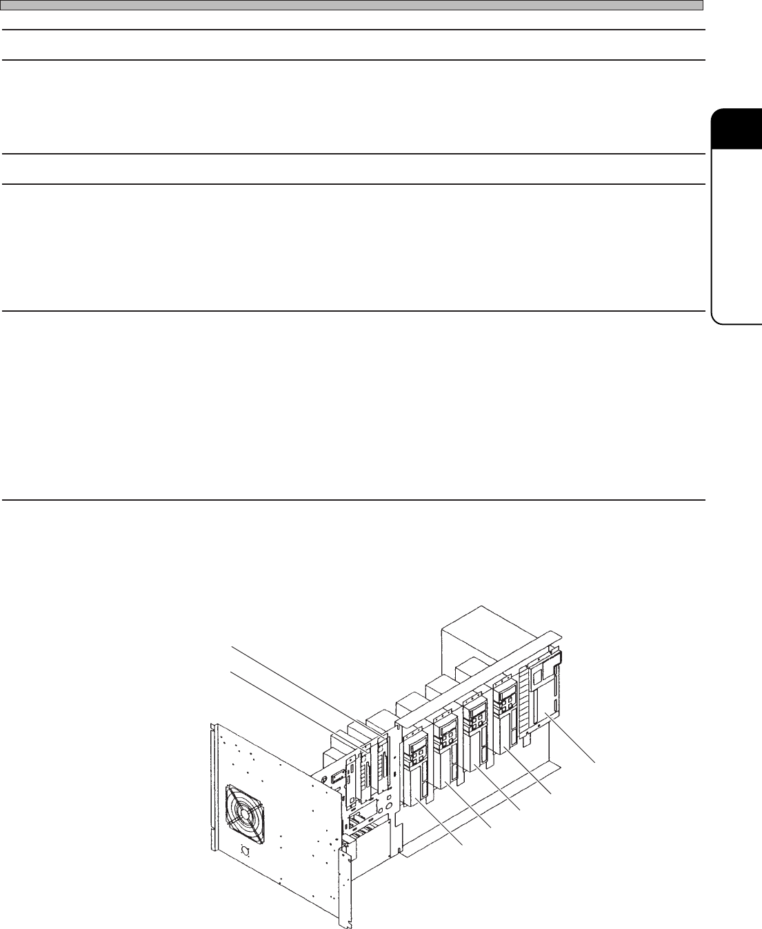
3-2-36 Hard Error
Parameter Error
Encoder Error
Acceleration Error
Voltage Error
Current Excess
Driver Error
1. Checking the error code and solutions
The driver of each axis has 7 segment LED and displays the error code.
Check the one for the driver of axis displayed as the error, and take the solutions in the list.
X-axis
A stage axis
Main axis
Tape feed changeover
Table Z-axis
330GC0AA
B stage axis
Y-axis