CM88Maintenace2x.PDF - 第95页
Page 1-3 CALIBRA TION 3Y3C-E-MMZ0A-A01-00 Mounting Position Calibration 1-1-2 Mounting Position Calibration Procedure T ransfer the data to the machine by performing 1 or 2 operation. 1. PT Operation According to the noz…
Page 1-2
3Y3C-E-MMZ0A-A01-00
1-1 Mounting Position Calibration
1-1-1 Preparation
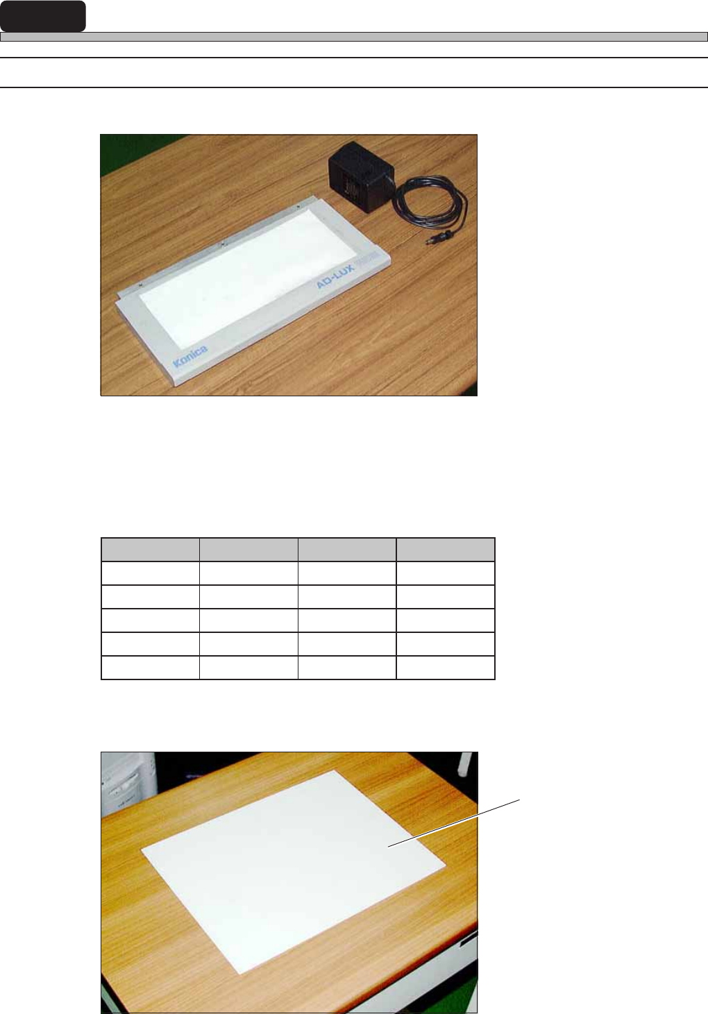
1. Light Source
2. Extension Cord
Prepare this for yourself.
3. Data (Floppy Disk or PT) and Chips
Main tact time = 0.1 s
4. Exclusively Reserved Board
Stick a double-sided tape on the mounting side.
elzzoN pihC feR GAM
5001R5001552
8061C8061152
5212C5212152
6123C6123152
3060C3060552
Exclusively Reserved Board
3Y3C-135P
3Y3C-134P
3Y3C-119TE
Page 1-3
CALIBRATION
3Y3C-E-MMZ0A-A01-00
Mounting Position Calibration
1-1-2 Mounting Position Calibration Procedure
Transfer the data to the machine by performing 1 or 2 operation.
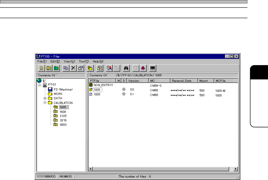
1. PT Operation
According to the nozzles (chips) to calibrate, select and transfer the data to the machine.
2. Floppy Operation
Transfer the data from the floppy disk to the machine.
733C-EPt-Fi-163
Page 1-4
3Y3C-E-MMZ0A-A01-01
Mounting Position Calibration
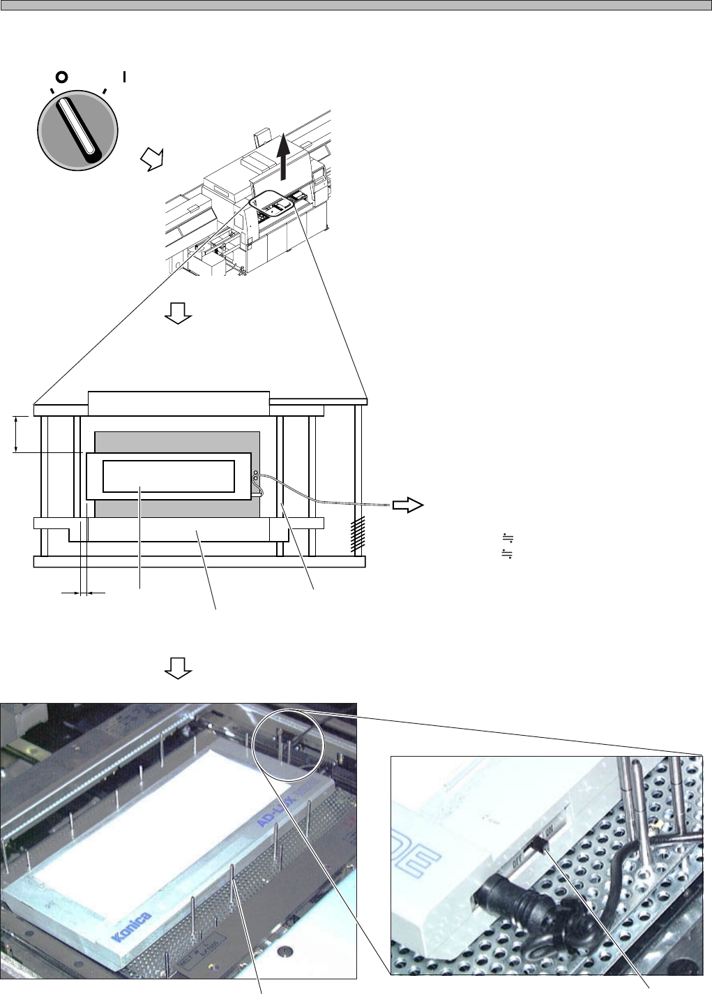
3. Setting the Jigs
1. Turn OFF the servo switch.
2. Open the front safety cover.
3. Fix the light source onto the board
holder by using the support pins.
∗ During calibration, the board holder raises and
lowers, and the X-Y table works. Be careful of
the light source position and that the cord is not
caught on.
Also be careful about the interference between
the extension cord and the linear bearing.
∗ Set 5 to 10 support pins.
∗ Support the cord with the support pins.
4. Turn ON the switch.
(Reference Side)
(To the Extension Cord)
A 5 mm
B 65 mm
Light Source
Board Holder Z Clamp
Linear Bearing
Switch
Support Pin
OFF ( )
ON ( )
SERVO
3Y3C-137P
A
B
4G3C-AB01
3Y3C-192E
3Y3C-136P