CM88Maintenace2x.PDF - 第97页
Page 1-5 CALIBRA TION 3Y3C-E-MMZ0A-A01-01 Mounting Position Calibration 5. Close the front safety cover . 6. Open the rear center safety cover . 7. Set the tape feeder at the No. 1 slot on the B stage. ∗ Set the chips th…
Page 1-4
3Y3C-E-MMZ0A-A01-01
Mounting Position Calibration
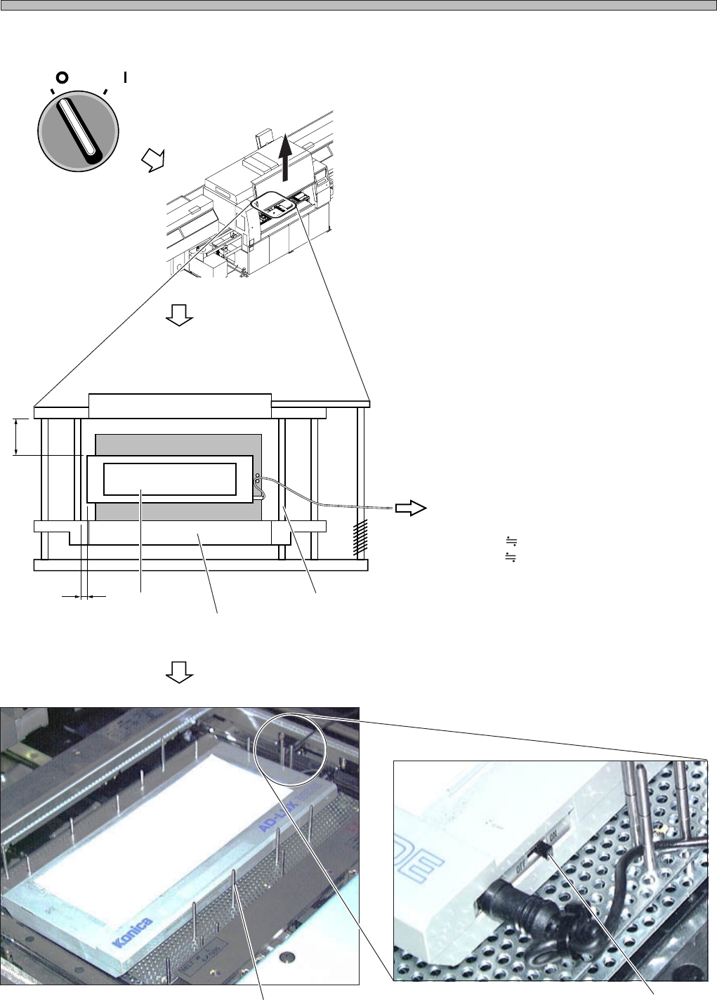
3. Setting the Jigs
1. Turn OFF the servo switch.
2. Open the front safety cover.
3. Fix the light source onto the board
holder by using the support pins.
∗ During calibration, the board holder raises and
lowers, and the X-Y table works. Be careful of
the light source position and that the cord is not
caught on.
Also be careful about the interference between
the extension cord and the linear bearing.
∗ Set 5 to 10 support pins.
∗ Support the cord with the support pins.
4. Turn ON the switch.
(Reference Side)
(To the Extension Cord)
A 5 mm
B 65 mm
Light Source
Board Holder Z Clamp
Linear Bearing
Switch
Support Pin
OFF ( )
ON ( )
SERVO
3Y3C-137P
A
B
4G3C-AB01
3Y3C-192E
3Y3C-136P
Page 1-5
CALIBRATION
3Y3C-E-MMZ0A-A01-01
Mounting Position Calibration
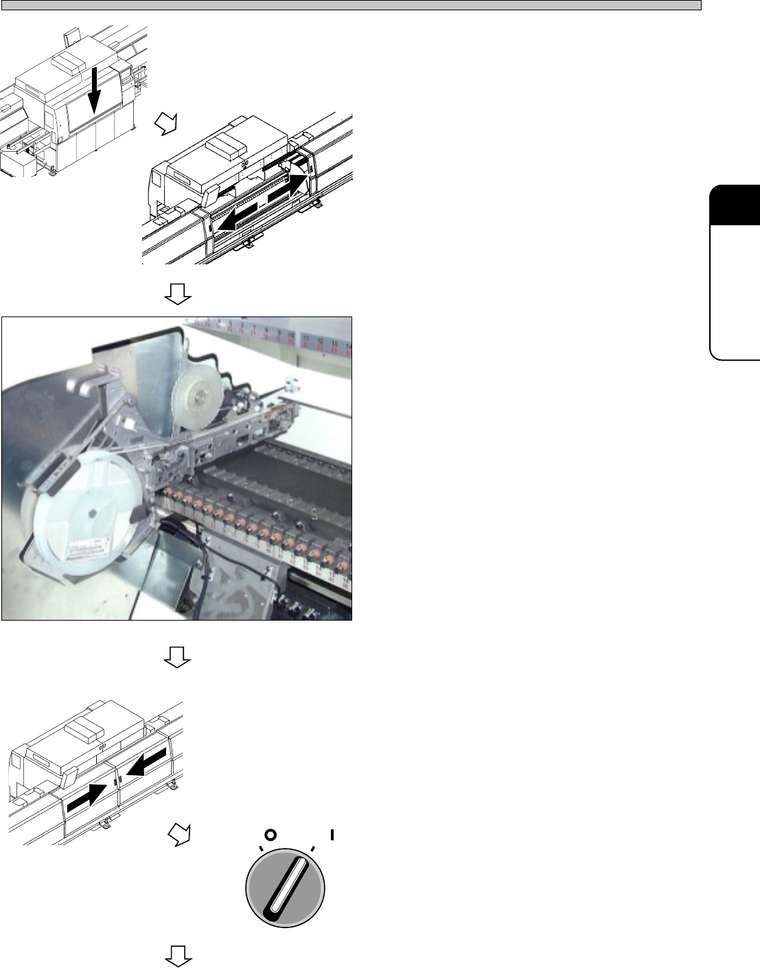
5. Close the front safety cover.
6. Open the rear center safety cover.
7. Set the tape feeder at the No. 1 slot on
the B stage.
∗ Set the chips that are selected from the data.
8. Close the rear center safety cover.
9. Turn ON the servo switch.
4G3C-AA01
3Y3C-138P
OFF ( )
ON ( )
SERVO
To the next page
3Y3C-AI01
3Y3C-AG01
Page 1-6
3Y3C-E-MMZ0A-A01-00
Mounting Position Calibration
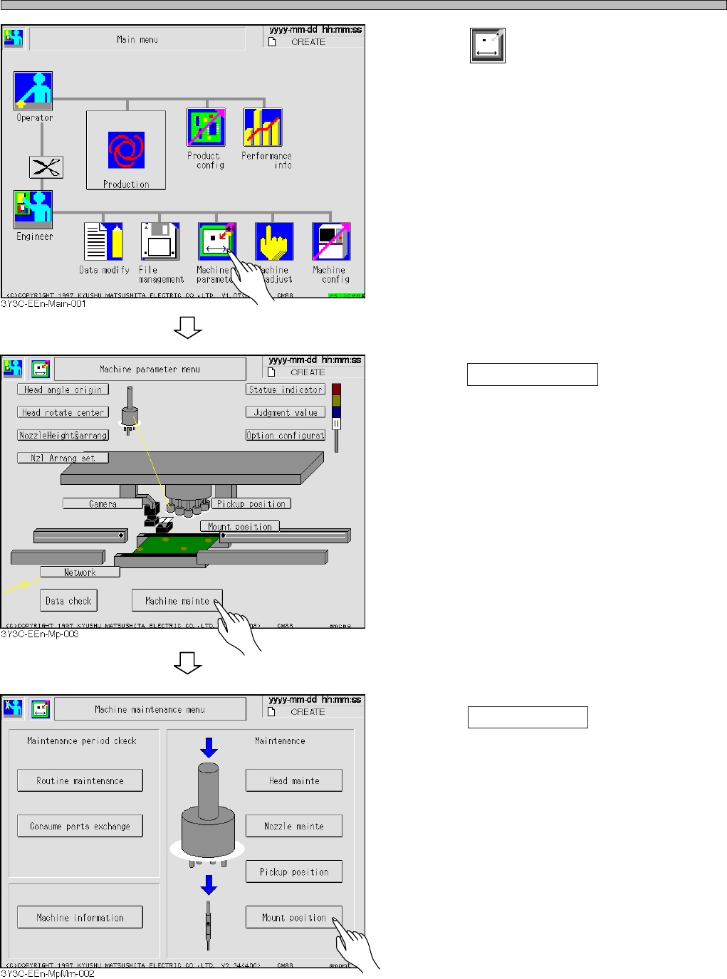
10. Press
Machine
parameter
.
11. Press Machine mainte .
12. Press Mount position .