00198611-01_IM_712.0_R18-2_EN.pdf - 第65页
Station Software Ver sion 712.0 (R18 - 2) / Installation Manual 11/2018 Edition 65 7.5 TX - Series (V1 and V2) Placemen t Machines ► When the TX placement machines are booted f or the first time y ou must select the foll…

Station Software Version 712.0 (R18-2) / Installation Manual 11/2018 Edition
64
7.3.1 SX1/SX2 (V2) Placement Machine
► When the SX1/SX2 (V2) placement machine is booted for the first time you must select the
following options manually:
– Table configuration for both locations.
– If the manual tray Carrier SX is used, the insert frame with the fold-away tape guide
channel is required. For this, the 60 slots (outer position, fold-away tape duct) table
configuration must be selected for each location concerned. Thus, the 27x27 reject bin and
the left reject channel on the location are excluded from the configuration.
CAUTION
If this setting is not made, the component may be rejected over the tray and the Z axis
may dash hard against the tray.
► If the Coplan computer has been installed, you must additionally confirm or reject the 3-D
Coplan sensor.
7.3.2 SX+ Placement Machine
If the SX+ placement machine is to be used without gantries, this has to be configured in the auto-
configuration after the machine has been booted.
► For this, select Ignore gantries at the processing area in the machine configuration dialog.
7.3.3 SX4 Placement Machine
► When the SX4 placement machine is booted for the first time you must select the SX4 Flexible
entry for Machine frame manually in the auto-configuration, if there are tables in outer position
in processing area 2, as this is not detected automatically via sensors.
Tables in outer position are used when stationary cameras are in use.
► Otherwise you select the SX4 High Speed entry.
7.4 DX-Series Placement Machines
► When the DX placement machines are booted for the first time you must select the following
options manually:
– For C&P12 placement head: height position (altitude)
– Lamp indicators (two-colored or three-colored)
– Table position:
inner 60 tracks
outer 60 tracks
outer with 30 tracks + free location for tray or WPC
– Confirm/reject 3-D Coplan sensor
Station Software Version 712.0 (R18-2) / Installation Manual 11/2018 Edition
65
7.5 TX-Series (V1 and V2) Placement Machines
► When the TX placement machines are booted for the first time you must select the following
options manually:
– If SIPLACE JTF-ML is used, select the X-Table, multi tray feeder support option for the
JTF-ML Table 40X on Location 1.
– If no reject plate has been installed, you must disable this option explicitly.
7.6 Checking/Updating the Embedded Software
If the correct embedded SW versions are not available on the machine, the machine boot gets
interrupted.
► In this case, perform an embedded SW download.
► Start an overall reference run for the machine.
7.7 Storage Location of the Machine Files (Calibration Data etc.)
The machine-specific configuration, measurement and parameter data is stored in XML files under
C:\Sirio\Work\Individual. These XML files contain all calibration data.
Station Software Version 712.0 (R18-2) / Installation Manual 11/2018 Edition
66
7.8 Necessary Calibration Steps
After the first booting of the station software, some calibration steps are required.
Requirements:
– The embedded SW versions have been updated.
– The reference run has been successfully performed.
– A calibration nozzle (1235) has to be available on every C&P20A placement head at
segment 1.
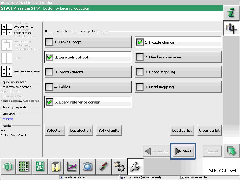
Figure 7-2: Required calibration steps
► Select the calibration steps that are highlighted in the figure and click on Next.
► Select all possible components in the following input masks (all conveyor lanes, all gantries, all
nozzle changers).