KE-750_MS.pdf - 第105页
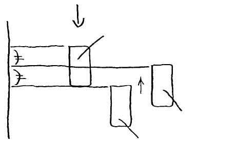
(14) Install one-shot repl acement base in main body. (15) Lowering the bank up detection sensor, fasten it in the gap between where the LED light goes on and off. LED light off Fasten here LED light on Fig. 9-5-3 1-98
(4) Shut off main air supply (hand valve).
(5) Remove screws holding drive cylinder assy on left and right sides.
(6) Raise bank lifter to remove (on replacement side).
(7) Remove the 4 screws holding bank up cylinder and remove cylinder.
(8) Switch connection of speed controller & bank up detector cable (left only) to the new cylinder.
Provisionally connect cable 10mm from top.
(9) Mount cylinder and insert bank lifter from above.
(10) Screw lifter cylinder shaft into cylinder rod.
(11) Open main air supply.
(12) Adjust speed control for left / right cylinders. (Refer to section9 - 6.)
(13) Mount drive cylinder assy.
1-97
(14) Install one-shot replacement base in main body.
(15) Lowering the bank up detection sensor, fasten it in the gap between where the LED light goes on
and off.
LED light off
Fasten here
LED light on
Fig. 9-5-3
1-98
6. Bank Up Cylinder Speed Control Adjustment
(Optional One-Shot Replacement Base)
Lock the speed control of the right cylinder and adjust the left speed control.
(At time of assembly, close upper cylinder completely then loosened 3 turns. Close lower cylinder
completely then loosened 4 turns.)
Remove cylinder box B to open.
UP Upper speed control adjusts ascending speed
If ascending speed of left cylinder is too quick, turn adjusting screw clockwise.
DOWN Lower speed control adjusts descending speed
If descending speed of left cylinder is too quick, turn adjusting screw clockwise.
Once up & down speeds of left & right cylinders are even, use the lock screw to lock the adjusting screw.
After locking the setting, operate UP/DOWN once again to verify.
1-99