KE-750_MS.pdf - 第108页
8. Selector Replacement (Optional One-Shot Replacement Base) (1) Shut off main air supply (hand valve). (2) Turn white cap of selector to the left to remove from cover (3) Transfer half union & silencer to new select…
7. Bank Up Detecting Sensor Replacement
(Optional One-Shot Replacement Base)
(1) Turn main power source OFF.
(2) Follow the same procedures (2) through (7) given in section 9 - 5.
(8) Loosen mounting screw and lower to remove.
(9) Reassemble in reverse sequence.
Mounting scre
w
Fig. 9-7-1
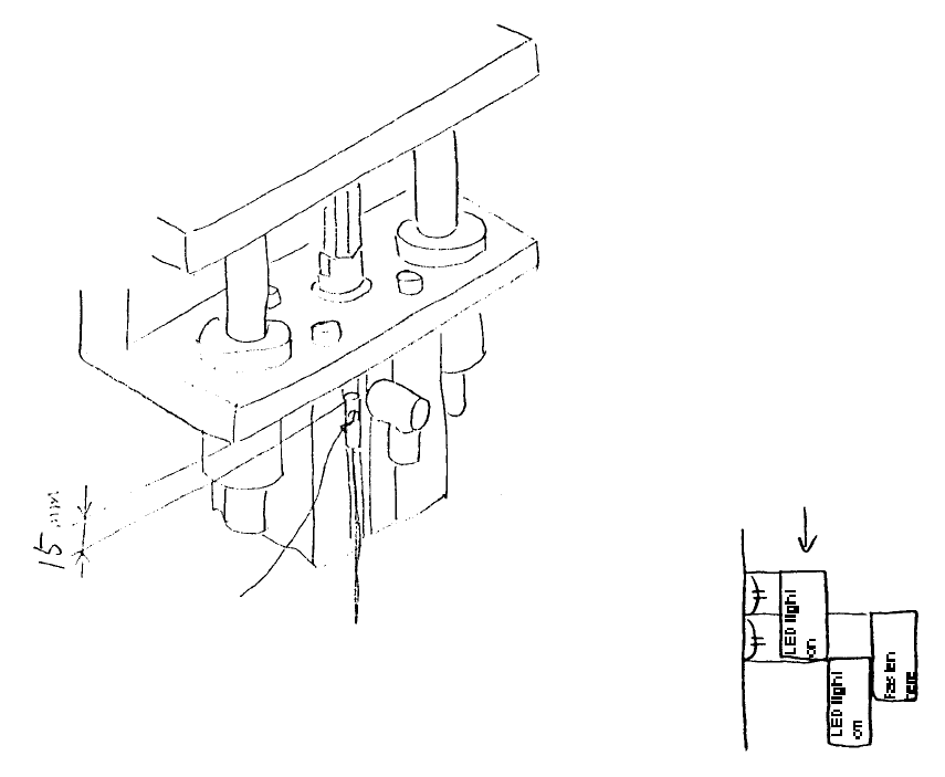
(Adjustment)
(1) Provisionally fasten cylinder 15mm from its upper max. position.
(2) Turn main power supply ON.
(3) nstall one-shot replacement base in mounter.
(4) Lowering the bank up detector sensor, fasten it in the gap between where the LED light goes on and
off.
(Bank up detector cable)
Lengths differ
Front E95577250A0
Rear E95587250A0
1-100
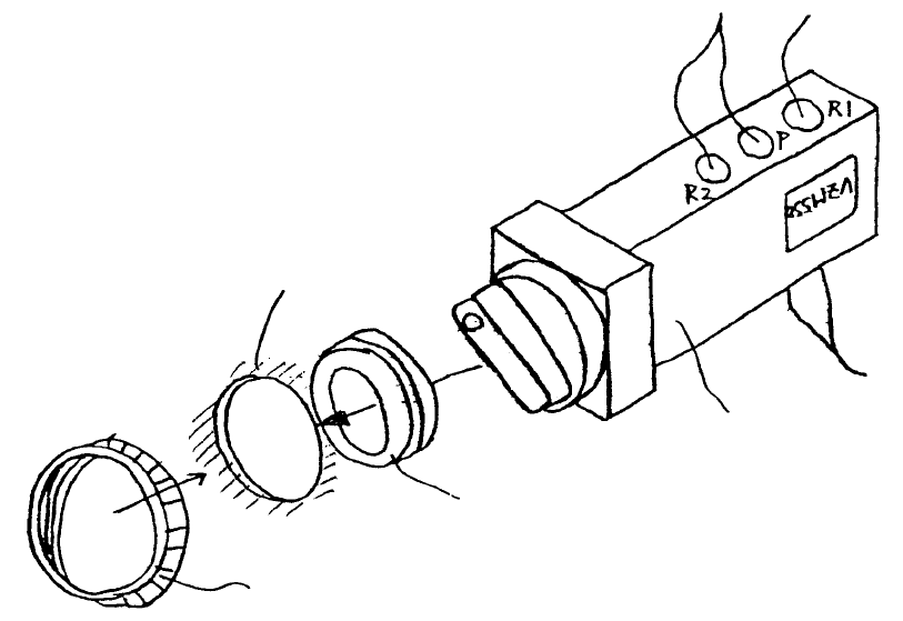
8. Selector Replacement
(Optional One-Shot Replacement Base)
(1) Shut off main air supply (hand valve).
(2) Turn white cap of selector to the left to remove from cover
(3) Transfer half union & silencer to new selector and attach selector to cover with cap.
(4) Open main air supply.
Front E27867259A0
Rear E27867210A0
Cap
Cover mounting hole
3 rubber rings
Selecto
r
PV0151170A0
Half union x 2
PJ301065103
PX055104000
Silencer
PJ304065103
Swivel elbow x 2
Selector ass
y
E27867250A0
Fig. 9-8-1
1-101
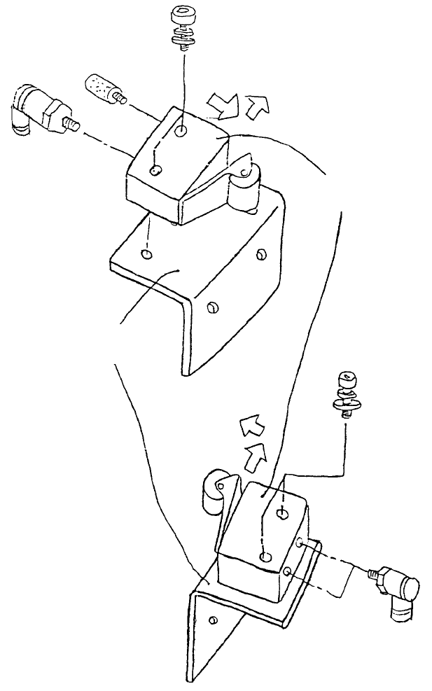
9. Roller Lever Replacement
(Optional One-Shot Replacement Base)
Carry out procedures after shutting off main air supply.
PJ304040505
Elbow union x 2
SL6042592TN
SEMS cap x 2
Roller leve
r
PV010505000
When fastening with M4
x 25, press roller lever in
direction of arrows and
fasten.
SL6042592TN
SEMS cap x 2
Right bank valve
assy
E2776721000
Bank valve plate
PJ304040505
Elbow union
PX050501000
Silencer
Left bank valve ass
y
Fig. 9-9-1
1-102