KE-750_MS.pdf - 第113页
Chapter 11 Switches 1. Push Button Switch Replacement For Switches: Start, Stop, Servo free, Single cycle, On line, Origin (1) Unplug connector to operation switch PWB. (2) Remove switch by pressing with hand on fitting …
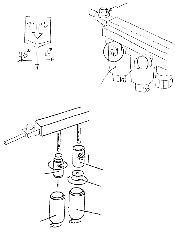
2. Filter Element Replacement
(1) Shut off hand valve.
(2) While pulling slide piece down, turn either left or right 45 in relation to main body and pull out.
(3) Remove air filter by rotating filter retainer and remove filter element B. Remove mist separator from
filter element A in the same manner.
(4) Reassemble in reverse sequence.
Mist separato
r
A
ir filte
r
PF901003000
Filter element B
Filter retaine
r
PF901002000
Filter element A
PF901002000
Filter element A
Main bod
y
Slide piece
Hand valve
Fig. 10-2-2
Fig. 10-2-2
1-105
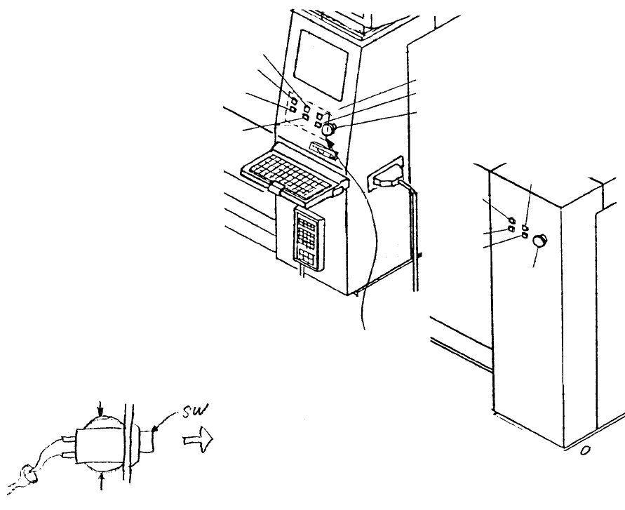
Chapter 11 Switches
1. Push Button Switch Replacement
For Switches: Start, Stop, Servo free, Single cycle, On line, Origin
(1) Unplug connector to operation switch PWB.
(2) Remove switch by pressing with hand on fitting on rear side of cover and pulling from the front.
* When replacing switches, connect the connector number of the operation switch PWB with the
matching cable bundle connector number.
Pull out
Press
Press
Operation
switch PWB
Rea
r
emergency
switch
Rear single
cycle switch
Rear stop
switch
Rear start
switch
Rear servo
free switch
Front servo free switch
Front emergency switch
Front single cycle switch
Front stop switch
Front origin switch
Front on line switch
Front start switch
Fig. 11-1-1
Fig. 11-1-2
Note: The cable bundle number = Operation switch PWB connector number + 7
(3) Reassemble in reverse sequence.
1-106
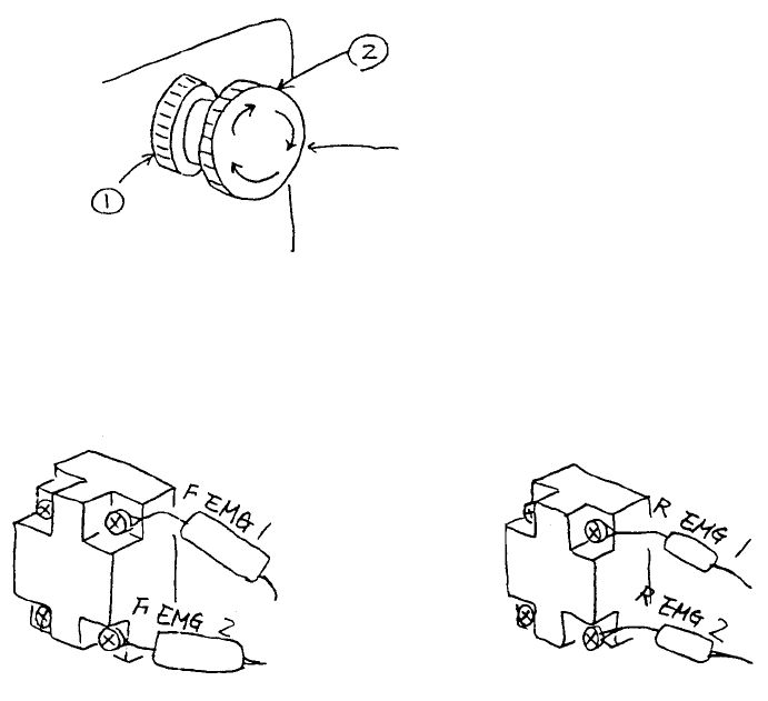
2. Emergency Stop Switch Replacement
(1) Remove emergency stop switch knobs (1) & (2) and remove switch from the back of the panel.
(2) Disconnect cable bundle in back side of switch with a screwdriver and replace switch.
* For replacement, connect cable bundle as shown below.
Front emergency switch Rear emergency switch
HA002040000
Push switch
Fig. 11-2-1
Fig. 11-2-2
1-107