KE-750_MS.pdf - 第114页
2. Emergency Stop Switch Replacement (1) Remove emergency stop switch knobs (1) & (2) and remove switch from the back of the panel. (2) Disconnect cable bundle in back side of switch with a screwdriver and replace sw…
Chapter 11 Switches
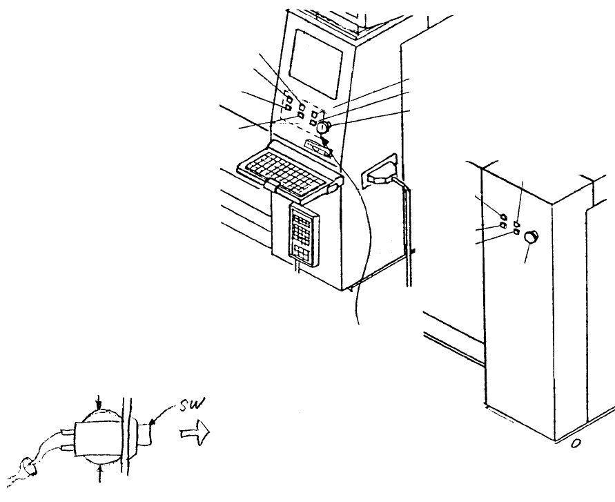
1. Push Button Switch Replacement
For Switches: Start, Stop, Servo free, Single cycle, On line, Origin
(1) Unplug connector to operation switch PWB.
(2) Remove switch by pressing with hand on fitting on rear side of cover and pulling from the front.
* When replacing switches, connect the connector number of the operation switch PWB with the
matching cable bundle connector number.
Pull out
Press
Press
Operation
switch PWB
Rea
r
emergency
switch
Rear single
cycle switch
Rear stop
switch
Rear start
switch
Rear servo
free switch
Front servo free switch
Front emergency switch
Front single cycle switch
Front stop switch
Front origin switch
Front on line switch
Front start switch
Fig. 11-1-1
Fig. 11-1-2
Note: The cable bundle number = Operation switch PWB connector number + 7
(3) Reassemble in reverse sequence.
1-106
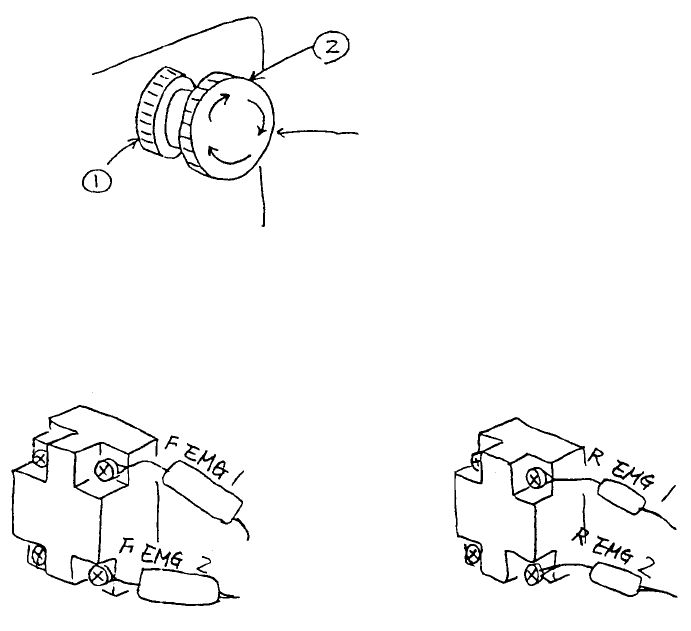
2. Emergency Stop Switch Replacement
(1) Remove emergency stop switch knobs (1) & (2) and remove switch from the back of the panel.
(2) Disconnect cable bundle in back side of switch with a screwdriver and replace switch.
* For replacement, connect cable bundle as shown below.
Front emergency switch Rear emergency switch
HA002040000
Push switch
Fig. 11-2-1
Fig. 11-2-2
1-107
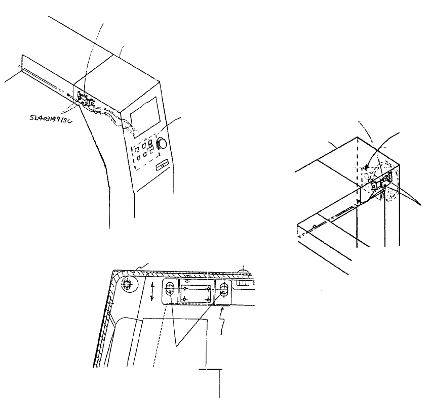
3. Front/Rear Cover Open Switch Replacement
(1) Remove connector from operation switch PWB.
(2) Cut away cable tie, remove stop screw (SL4031491SC) and replace.
(3) After replacing, adjust cover open switch.
Method
– Loosen both cover open switch screws and move up & down. Fasten in the position where limit
switch clicks.
(4) Reassemble in reverse sequence.
Cover open switch
bracket
Cover open
switch bracket
screw
Front of safety cove
r
Cover open switch
bracket adjustment
Operation switch PWB connector position
Front cover open switch CN726
Rear cover open switch CN736
Operation
switch PWB
Cover RUL
Front cove
r
open switch
Operation
switch PWB
Cover FUR
Front cover open switch
Fig. 11-3-1
Fig. 11-3-2
Fig. 11-3-3
1-108