KE-750_MS.pdf - 第119页
Chapter 13 CRT 1. Image Monitor Replacement (1) Remove connector of monitor power cable and remove image monitor. (2) Remove image monitor cable at the rear of the CRT head. (3) Lower button at the bottom of the head and…
1. Sensor Replacement
(1) Turn main power OFF.
(2) Cut cable tie with pliers and remove mounting screw (1).
(3) Reassemble in reverse sequence.
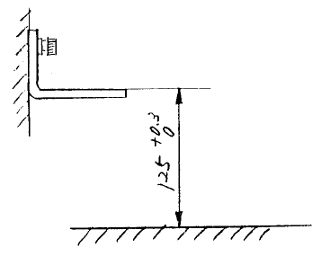
2. Sensor Height Adjustment
Sensor height adjustment is necessary when FS bracket has become bent.
(1) Loosen FS bracket mounting screw until spring washer yields.
(2) Adjust FS bracket so that its top face is 125 +0.3/0mm from top face of bank. Also, left & right FS
brackets (receptor & projector) must have a height variance no greater than 0.1mm.
Upper surface of bank
Upper surface of bank
Fig. 12-1-2
3. Beam Alignment
(1) Turn main power ON.
(2) Move projector & receptor to align beam. When in alignment, both red & green LED in the receptor
will light. (Red signals movement, green signals all safe.)
1-111
Chapter 13 CRT
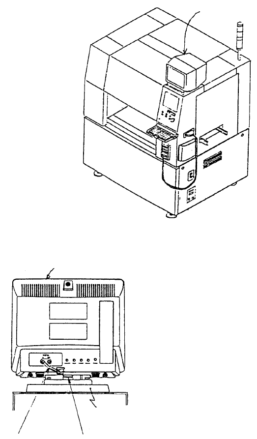
1. Image Monitor Replacement
(1) Remove connector of monitor power cable and remove image monitor.
(2) Remove image monitor cable at the rear of the CRT head.
(3) Lower button at the bottom of the head and slide head towards the front of the machine. Lift head
and replace.
(4) Reassemble in reverse sequence.
Base
Button
Image monitor cable
Head
Image monito
r
Fig. 13-1-1
Fig. 13-1-2
1-112
Chapter 14 Floppy Disk Drive (FDD)
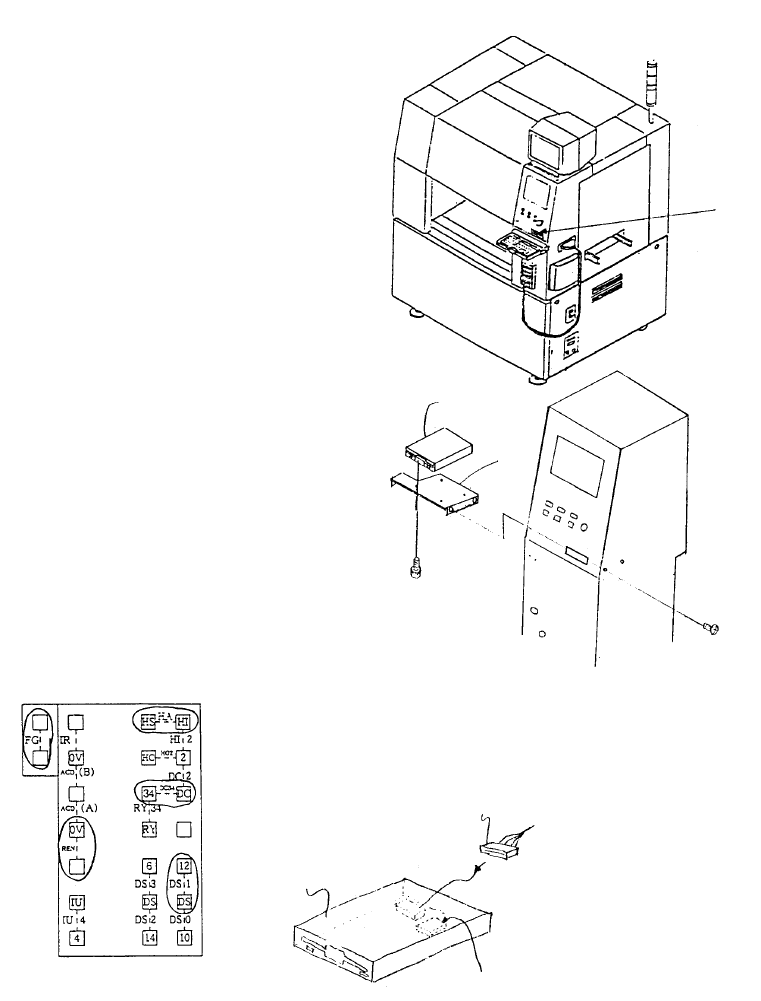
1. Floppy Disk Drive Replacement
(1) Adjust jumper switch settings on new floppy disk drive to match those shown below.
(2) Remove FDD bracket.
(3) Remove the 2 connectors, remove and replace floppy disk drive.
(4) Reassemble in reverse sequence.
Jumper switch
E9433725000
FDD relay cable
E9606715000
3.5" Floppy disk
Insert jumpers at locations circled
Jumper Switch Setting Diagram
SM0061201SC
SL4030691SC
FDD
support
FDD
Floppy disk drive
Fig. 14-1-1
Fig. 14-1-2
Fig. 14-1-3
1-113