KE-750_MS.pdf - 第120页
Chapter 14 Floppy Disk Drive (FDD) 1. Floppy Disk Drive Replacement (1) Adjust jumper switch settings on new fl oppy disk drive to match those shown below. (2) Remove FDD bracket. (3) Remove the 2 connectors, remove and …
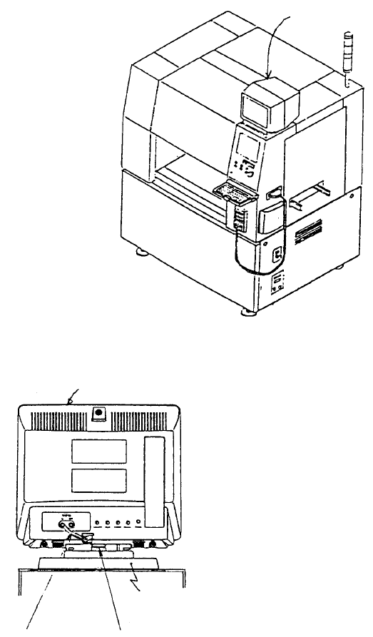
Chapter 13 CRT
1. Image Monitor Replacement
(1) Remove connector of monitor power cable and remove image monitor.
(2) Remove image monitor cable at the rear of the CRT head.
(3) Lower button at the bottom of the head and slide head towards the front of the machine. Lift head
and replace.
(4) Reassemble in reverse sequence.
Base
Button
Image monitor cable
Head
Image monito
r
Fig. 13-1-1
Fig. 13-1-2
1-112
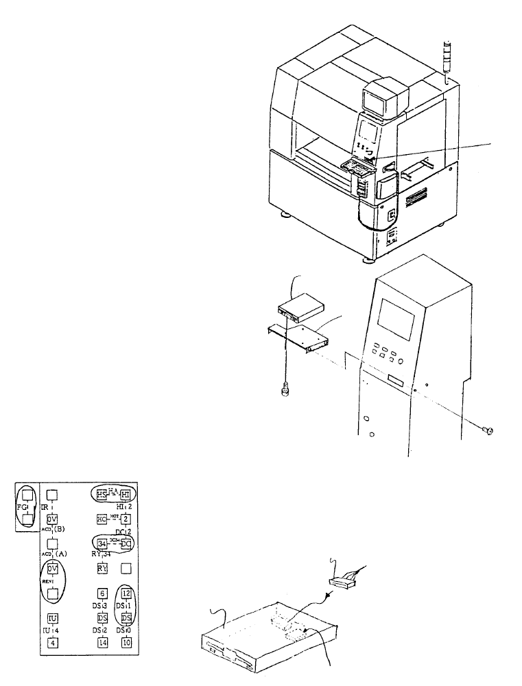
Chapter 14 Floppy Disk Drive (FDD)
1. Floppy Disk Drive Replacement
(1) Adjust jumper switch settings on new floppy disk drive to match those shown below.
(2) Remove FDD bracket.
(3) Remove the 2 connectors, remove and replace floppy disk drive.
(4) Reassemble in reverse sequence.
Jumper switch
E9433725000
FDD relay cable
E9606715000
3.5" Floppy disk
Insert jumpers at locations circled
Jumper Switch Setting Diagram
SM0061201SC
SL4030691SC
FDD
support
FDD
Floppy disk drive
Fig. 14-1-1
Fig. 14-1-2
Fig. 14-1-3
1-113
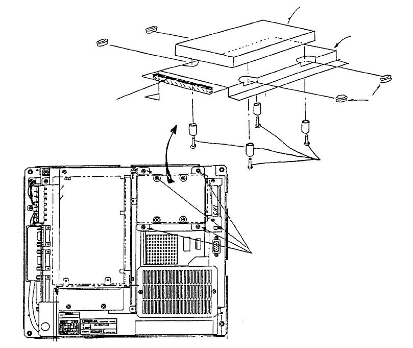
Chapter 15 Hard Disk Drive (HDD)
1. HDD Replacement
(1) Remove flat cable connector CN1 in Mother 2 board.
(2) Remove 4 sheet metal screws (1) holding hard disk.
(3) Remove 4 screws (2).
(4) Remove HDD. (Note: Be careful not to let rubber bushes or spacers create debris.)
(5) Reassemble in reverse sequence.
(Bottom)
View o
f
back face o
f
panel computer
Mounting
plate
(Top)
Mother 2 board
Screw (1) x 4
Note: Scre
w
s, round column
spacers and rubber bushes are
accessories to panel computer.
Screw x 4
Spacer x 4
Rubber bush x 4
Panel computer (Top)
Mounting plate
HDD (Hard disk drive)
Panel computer (Bottom)
Fig. 15-1-1
Fig. 15-1-2
1-114