KE-750_MS.pdf - 第122页
Chapter 16 Panel Computer 1. Panel Computer Replacement (1) Remove the following: 94377250A0 Printer cable 95807250A0 Track ball cable 92367250A0 Power cable (2) Remove the 6 flange nuts. (3) Remove the 4 plate screws to…
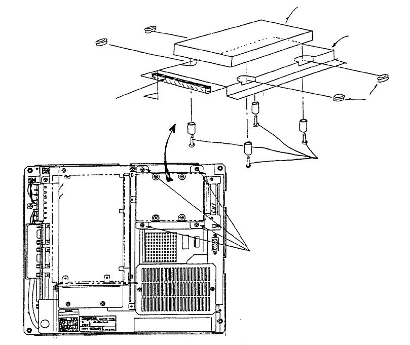
Chapter 15 Hard Disk Drive (HDD)
1. HDD Replacement
(1) Remove flat cable connector CN1 in Mother 2 board.
(2) Remove 4 sheet metal screws (1) holding hard disk.
(3) Remove 4 screws (2).
(4) Remove HDD. (Note: Be careful not to let rubber bushes or spacers create debris.)
(5) Reassemble in reverse sequence.
(Bottom)
View o
f
back face o
f
panel computer
Mounting
plate
(Top)
Mother 2 board
Screw (1) x 4
Note: Scre
w
s, round column
spacers and rubber bushes are
accessories to panel computer.
Screw x 4
Spacer x 4
Rubber bush x 4
Panel computer (Top)
Mounting plate
HDD (Hard disk drive)
Panel computer (Bottom)
Fig. 15-1-1
Fig. 15-1-2
1-114
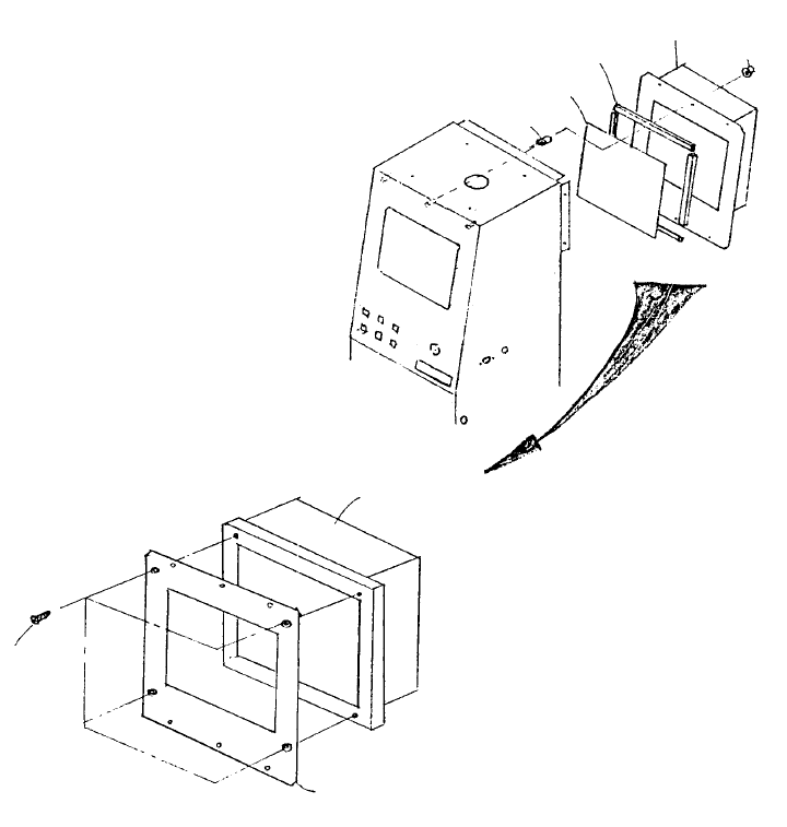
Chapter 16 Panel Computer
1. Panel Computer Replacement
(1) Remove the following:
94377250A0 Printer cable
95807250A0 Track ball cable
92367250A0 Power cable
(2) Remove the 6 flange nuts.
(3) Remove the 4 plate screws to remove PC bracket. Remove panel computer at the same time.
(4) Reassemble in reverse sequence.
E1340725000
PC bracket
SM1030601SN
Plate screw x 4
E9601725000
Panel computer
Flush nut x 6
NM3040520SF
E1345725000
LCD sheet
E5776172000
Top cover packing PU
E5776172000
Panel computer
B412280400
0
FIG. 16-1-1
Fig. 16-1-2
1-115
Chapter 17 Electric Parts
1. Electric Parts Layout
Dia. 17 - 1 - 1 / 2 are found on the following page.
Parts Names
1 Image monitor
2 Panel computer
(Front: ARCNET PWB assy, operation PWB assy, operation switch PWB assy, HDD)
3 Signal light
4 FDD
5 Key board
6 HOD
7 Power switch
8 Power transformer
9 Power unit
10 X-Y axis AC servo driver
11 Z/θ axis AC servo driver
12 Control unit
(Sub-CPU PWB assy, AC servo control PWB assy, Z/θ control PWB assy,
I/O control PWB assy, Matching PWB assy, IMG-P PWB assy.
Optional: L.L.L PWB verification PWB assy)
13 Magnescale detector
14 LA/LAHD unit
15 Base unit (PWB assy)
16 Feeder unit (PWB assy)
17 Feeder interface (PWB assy) (Front / Rear)
18 Head unit
Head main PWB assy, Head motor PWB assy.
Optional: HMS, Bad mark sensor)
19 OCC camera & light (PWB assy) (Left / Right)
1-116