KE-750_MS.pdf - 第124页
Fig. 17-1-1 Front View Diagram Fig. 17-1- 2 Rear View Diagram 1-117
Chapter 17 Electric Parts
1. Electric Parts Layout
Dia. 17 - 1 - 1 / 2 are found on the following page.
Parts Names
1 Image monitor
2 Panel computer
(Front: ARCNET PWB assy, operation PWB assy, operation switch PWB assy, HDD)
3 Signal light
4 FDD
5 Key board
6 HOD
7 Power switch
8 Power transformer
9 Power unit
10 X-Y axis AC servo driver
11 Z/θ axis AC servo driver
12 Control unit
(Sub-CPU PWB assy, AC servo control PWB assy, Z/θ control PWB assy,
I/O control PWB assy, Matching PWB assy, IMG-P PWB assy.
Optional: L.L.L PWB verification PWB assy)
13 Magnescale detector
14 LA/LAHD unit
15 Base unit (PWB assy)
16 Feeder unit (PWB assy)
17 Feeder interface (PWB assy) (Front / Rear)
18 Head unit
Head main PWB assy, Head motor PWB assy.
Optional: HMS, Bad mark sensor)
19 OCC camera & light (PWB assy) (Left / Right)
1-116
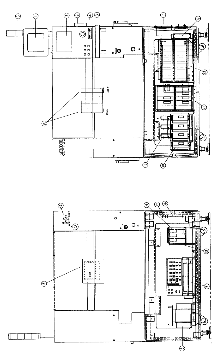
Fig. 17-1-1 Front View Diagram Fig. 17-1- 2 Rear View Diagram
1-117
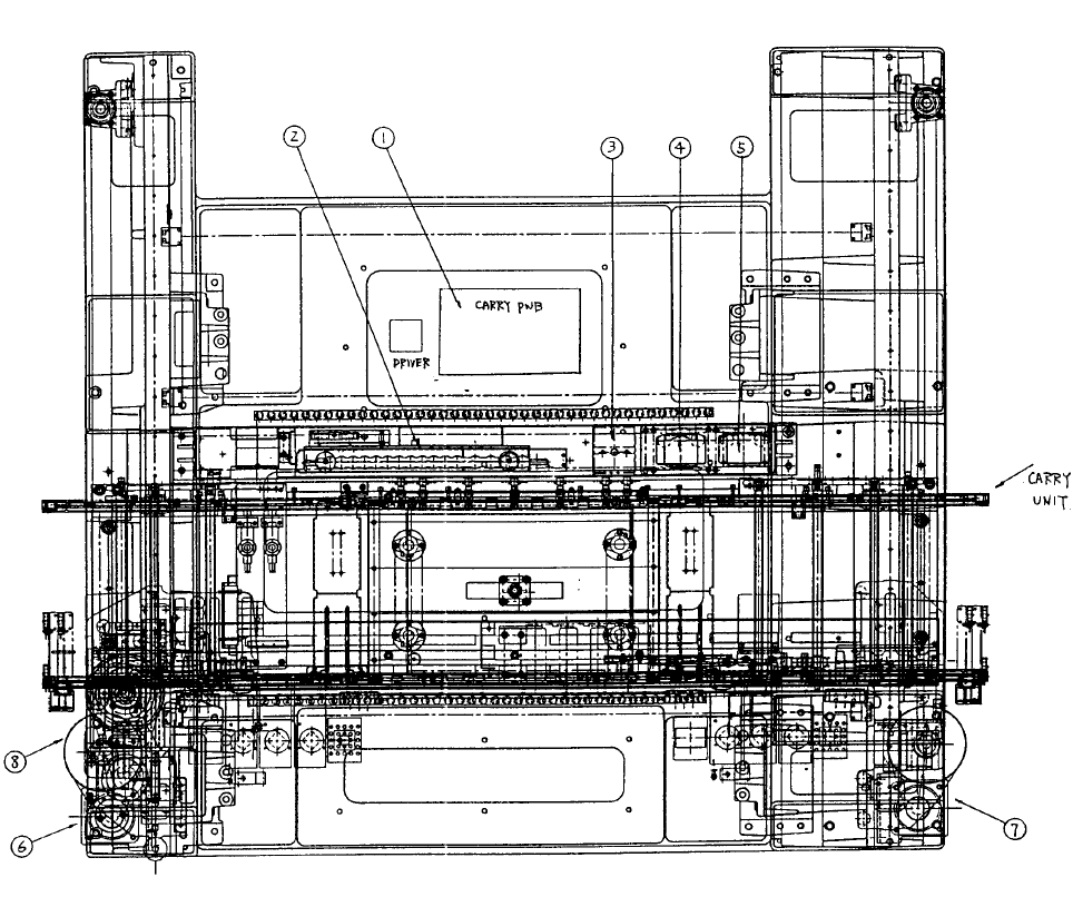
2. Base Superstructure Layout
Dia. 17 - 2 - 1 provides a drawing of the superstructure.
Parts Names
1 Conveyor unit (PWB assy) (5 phase stepping driver)
2 ATC unit
3 CAL light (PWB assy)
4 0.4mm VCS camera & light [Optional: BGA light (PWB assy)]
5 Optional: 0.3mm VCS camera & light [Micro BGA light (PWB assy)]
6 Y left axis AC servo motor
7 Y right axis AC servo motor
8 X axis AC servo motor
Fig. 17-2-1 Base Frame Construction
1-118