KE-750_MS.pdf - 第126页
Electric Parts Structure 1-119
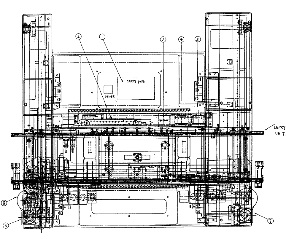
2. Base Superstructure Layout
Dia. 17 - 2 - 1 provides a drawing of the superstructure.
Parts Names
1 Conveyor unit (PWB assy) (5 phase stepping driver)
2 ATC unit
3 CAL light (PWB assy)
4 0.4mm VCS camera & light [Optional: BGA light (PWB assy)]
5 Optional: 0.3mm VCS camera & light [Micro BGA light (PWB assy)]
6 Y left axis AC servo motor
7 Y right axis AC servo motor
8 X axis AC servo motor
Fig. 17-2-1 Base Frame Construction
1-118
Electric Parts Structure
1-119
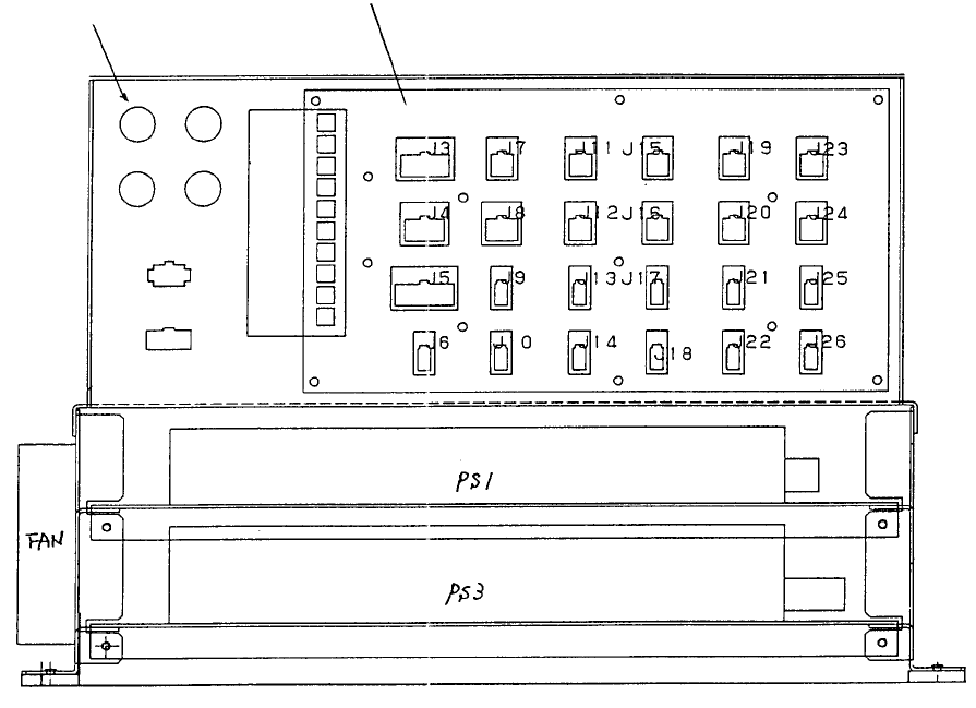
3. Electrical Unit Layout
3-1 Electrical Unit Layout Structure
The power unit is installed at the back center. Dia. 17 - 3 - 1 shows the structure. The power unit is
composed of DC power, control relays, circuit protectors, etc., and supplies power to all other units (X-Y
unit, head unit, control unit, conveyor unit).
Panel PWB
Circuit protecto
r
PS2, 4, 5 are installed on the back side of the panel PWB.
Fig. 17-3-1 Power Unit Structure Diagram
For instructions on DC power adjustment, refer to QA Table, Electricals, EL-1.
1-120