KE-750_MS.pdf - 第131页
Mount feeder interface PWB A assy (E8618721AA0 ) to the right side of the control unit. Feeder I/F PWB A Assy Fan Fan Fig. 17-4-2 Mounting of Feeder I/F PWB 1-123
4. Control Unit
4-1 Control Unit Structure
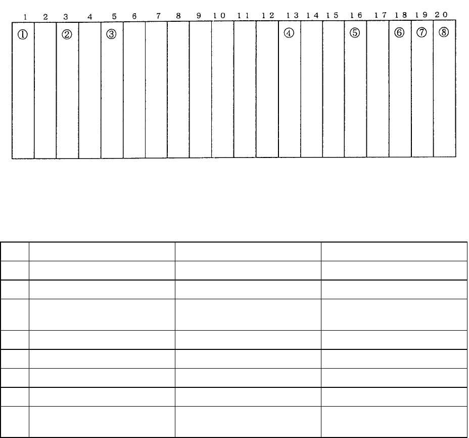
Dia. 17 - 4 - 1 shows PWB distribution in the control unit and Table 17 - 4 - 1 provides the relevant part
numbers. Refer to these to check the PWB assy.
Slot No. 20 Slots
Fig. 17 - 4 - 1 PWB Wiring Diagram (Front view of rack)
Table 17-4-1 Correlation of Parts Numbers
No. Part No. PWB Assy Name Comments
1 E86017210A0 Sub CPU PWB assy (Main)
2 E86027210A0 AC servo control PWB assy
3 E86017250A0
E8601725AA0
Z/θ control PWB assy
Z/θ control PWB A assy
For KE-750
For KE-760
4 E86057210A0 I/O control PWB assy
5 E86317210A0 MATCHING PWB assy
6 E86107210A0 IMG-P PWB assy
7 E86717050A0 VERFY I/F PWB assy Optional
8 E9710721000
(Accessory PWB)
L.L.L PWB Optional
Note: PWB assemblies (5) & (6) should only be connected to the slots indicated in Dia. 17 - 4 - 1.
Improper connection will result in the damage of IC's in every PWB when power is supplied.
1-122
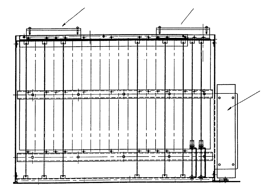
Mount feeder interface PWB A assy (E8618721AA0) to the right side of the control unit.
Feeder I/F
PWB A Assy
FanFan
Fig. 17-4-2 Mounting of Feeder I/F PWB
1-123
4-2 PWB Assy Jumper Setting
All PWB assy jumper settings in the control unit are completed prior to receipt of the machine but
please confirm when making the settings for the other PWB assemblies. Refer to the PWB assy
drawing for PWB jumper settings.
(1) E86017210A0 Sub CPU PWB assy (Main)
(2) E86027210A0 AC servo control PWB assy
(3) E86017250A0 Z/θ control PWB assy (special KE-750 PWB)
(4) E86017250A0 Z/θ control PWB A assy (special KE-760 PWB)
(5) E86057210A0 I/0 control PWB assy
(6) E86317210A0 MATCHING PWB assy
(7) E86107210A0 IMG-P PWB assy
(8) E86207210A0 Back board PWB assy
Set KE-750 & KE-760 (common) as follows:
Jumper W No's.
W4, W79 (Signal name: BG3)
W5, W15, W25, W65, W80, W90 (Signal name: IACK)
Open all 8 of the above jumpers.
1-124