KE-750_MS.pdf - 第132页
4-2 PWB Assy Jumper Setting All PWB assy jumper settings in the control unit ar e completed prior to receipt of the machine but please confirm when making the settings for the ot her PWB assemblies. Refer to the PWB assy…
Mount feeder interface PWB A assy (E8618721AA0) to the right side of the control unit.
Feeder I/F
PWB A Assy
FanFan
Fig. 17-4-2 Mounting of Feeder I/F PWB
1-123
4-2 PWB Assy Jumper Setting
All PWB assy jumper settings in the control unit are completed prior to receipt of the machine but
please confirm when making the settings for the other PWB assemblies. Refer to the PWB assy
drawing for PWB jumper settings.
(1) E86017210A0 Sub CPU PWB assy (Main)
(2) E86027210A0 AC servo control PWB assy
(3) E86017250A0 Z/θ control PWB assy (special KE-750 PWB)
(4) E86017250A0 Z/θ control PWB A assy (special KE-760 PWB)
(5) E86057210A0 I/0 control PWB assy
(6) E86317210A0 MATCHING PWB assy
(7) E86107210A0 IMG-P PWB assy
(8) E86207210A0 Back board PWB assy
Set KE-750 & KE-760 (common) as follows:
Jumper W No's.
W4, W79 (Signal name: BG3)
W5, W15, W25, W65, W80, W90 (Signal name: IACK)
Open all 8 of the above jumpers.
1-124
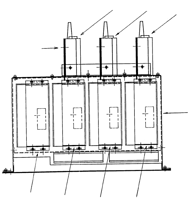
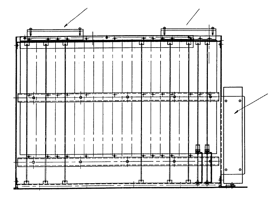
5. XY Unit
The XY unit is made up of AC servo drivers for XY axis drive and magnescales to detect positioning.
5-1 XY Unit Structure
The XY unit is contains of 2 AC servo drivers for the Y-axis, 1 AC servo driver for the X-axis and 1
condenser unit. In the top of each AC servo driver is a magnescale detector for the corresponding axis.
(AC servo driver)
Condenser unit
A
C servo
driver
YR axis
YL axisX axis
Magnescale
detector
YR axis
YL axisX axis
Fig. 17-5-1 XY Unit Structure
1-125