KE-750_MS.pdf - 第14页
3. Servo Motor Replacement (1) X Motor – Loosen lock nut NM6050001SC and SM8053002TP. 80 kg•cm Wi d e Narro w E9611721000 (T i ghteni ng torque 9Nm ) E9611721000 X-ax is m otor XM brac ket E2408725000 Left X fram e end S…
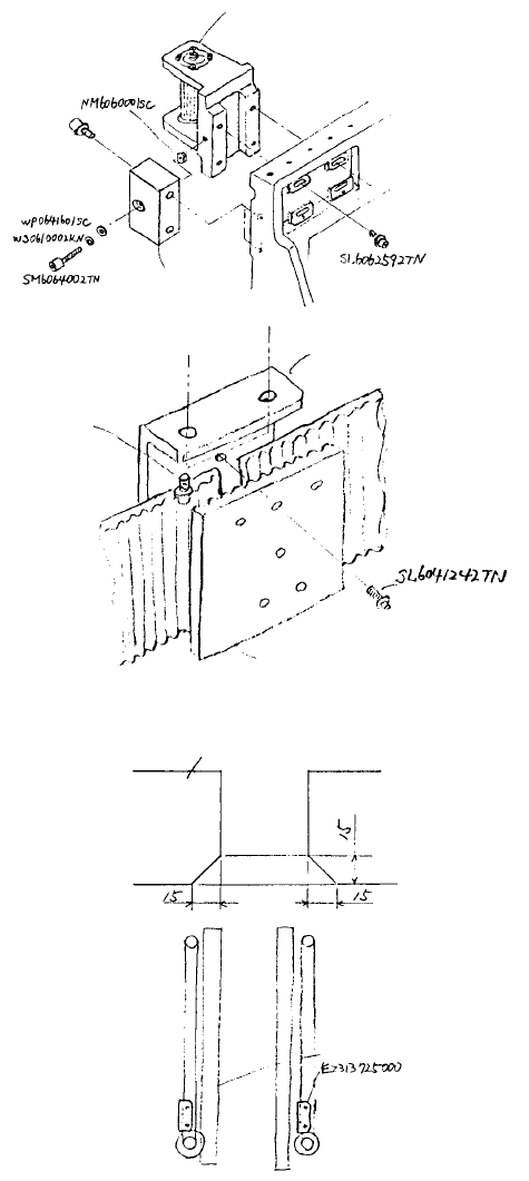
(4) YB Pulley Bracket Assy
– Remove the 2 screws SL6061642TN
holding Y belt support (1) at left & right
of X frame end.
(Tightening torque
15Nm)
Y tension support
E2315725000
Y belt support (1)
Timing belt YB
Y belt support (2)
Y belt support (1)
SL6061642TN
(Tightening torque
15Nm)
SL6062542TN
(Tightening torque
15Nm)
YB pulley bracket
assy (L/R)
– Loosen lock nut NM6060001SC at left
& right of YB pulley bracket and
loosen SM6064002TN.
– Loosen the 4 screws SL6062592TN
holding YB pulley bracket to loosen
belt.
– Remove the 6 screws SL6041242TN
holding Y belt support and remove Y
belt support (2).
– Remove the 4 screws SL6062592TN
and replace YB pulley bracket assy.
– Pass belt through pulleys YA & YB,
sandwich with Y belt support (1) and
fasten with screws. Move X belt
support up to 4 peaks left or right to
align mesh. Tighten the 6 screws
SL6041242TN evenly to a torque of
5Nm using Locktite 277.
– Tighten screws SL6061642TN holding
Y belt support (1) at left & right of X
frame end to regulate tension. Refer
to the QA Table, X-Y Unit, XY-1, XY
Belt Tension for Timing Belt YB.
1-7
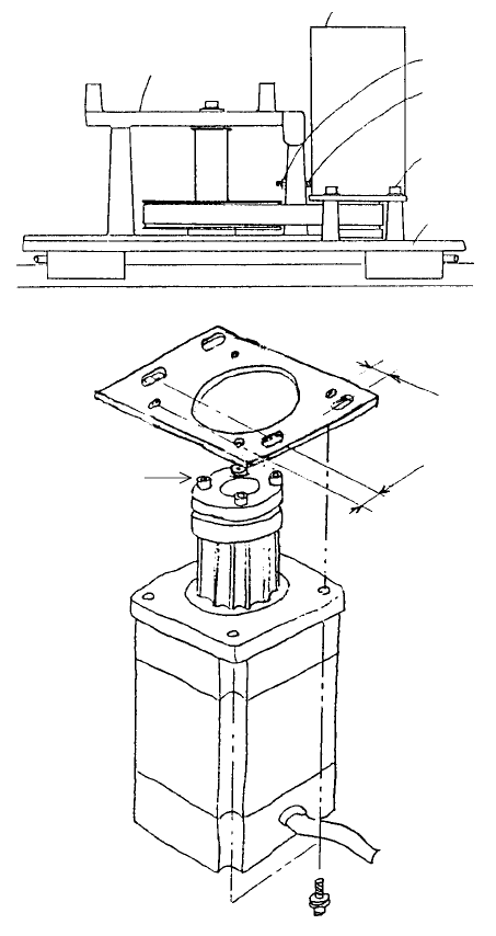
3. Servo Motor Replacement
(1) X Motor
– Loosen lock nut NM6050001SC
and SM8053002TP.
80 kg•cm
Wide
Narrow
E9611721000
(Tightening torque
9Nm)
E9611721000
X-axis motor
XM bracket
E2408725000
Left X frame end
SL6051492TN
SM8053002TP
NM6050001SC
XM bracket assy
XA pulley bracket assy
– Remove the 4 screws
SL6051492TN holding XM bracket
assy to left of X frame end and
remove bracket.
– Replace motor as shown in the
diagram while taking care to note
hole & tap positioning as well as
motor cable orientation.
– Remove pulley M and ETP bush
above motor axis and replace.
(Refer to separate section for
mounting & disassembly of ETP
bush.)
– Mount belt on pulley and
provisionally tighten screws
SL6051492TN.
– Regulate belt tension. Refer to the
QA Table, X-Y Unit, XY-1, XY Belt
Tension for Timing Belt XA.
1-8
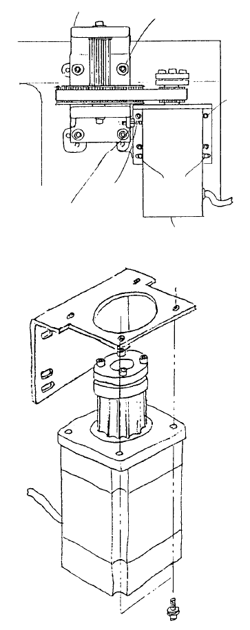
(2) Y Motor
SL6051492TNx4
(Tightening torque
9Nm)
Y-axis motor
KM000000020
YM bracket
E2305725000
YM bracket assy
SM8053002TP
SN6050001SC
Parallel
pins
SL6061642TN
(Tightening
torque 15Nm)
SL6061642TN
(Tightening torque 15Nm)
YA pulley bracket assy
– Loosen lock nut NM6050001SC and
SM8053002TP.
– Remove 4 screws SL6061642TN fastening
YM bracket assy Y frame and remove
bracket.
– Replace motor as shown in the diagram
while taking care to note motor & bracket
positioning. (Assemble so that motor cable
faces bracket motor mounting face.)
– Remove pulley M and ETP bush above
motor axis and replace. (Refer to separate
section for mounting & disassembly of ETP
bush.)
– Mount belt on pulley, insert parallel pin into
slot and provisionally tighten screws
SL6061642TN.
– Regulate belt tension. Refer to the QA Table,
X-Y Unit, XY-1, XY Belt Tension for Timing
Belt XA.
1-9