KE-750_MS.pdf - 第153页
11. Panel Computer Set-up 11.1 Method of Mounting Hard Disk (1) Remove flat cable connector from CN1 of Mother 2 PWB. (2) Remove 4 sheet metal screws from hard disk mounting plate. (3) Insert rubber bushes into hard disk…
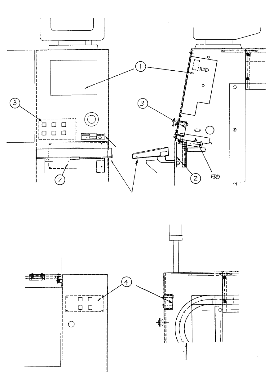
Y puller rail
Keyboard
Fig. 17-10-1 Front / Side Structural Diagram
Fig. 17-10-2 Rear Structural Diagram
1-137
11. Panel Computer Set-up
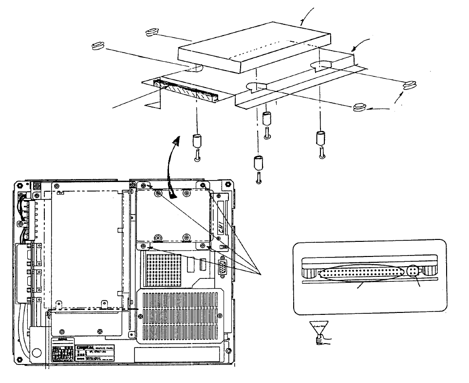
11.1 Method of Mounting Hard Disk
(1) Remove flat cable connector from CN1 of Mother 2 PWB.
(2) Remove 4 sheet metal screws from hard disk mounting plate.
(3) Insert rubber bushes into hard disk mounting plate.
(4) Place hard disk onto hard disk mounting plate.
(5) Fasten with the screws for the hard disk.
(6) Plug in flat cable connector to CN1 of Mother 2 PWB.
(7) Plug flat cable connector into hard disk.
(8) Screw hard disk mounting plate onto main body.
HDD Connector Front
Di
These 4 pins
are not used.
Cable is
plugged in here.
(Bottom)
View of back face of panel compute
r
Scre
w
(1) x 4
Mounting
plate
(Top)
Mother 2 board
Note: Screws, round column
spacers and rubber bushes are
accessories to panel computer.
Screw x 4
Spacer x 4
Caution: Imprope
r
connection may lead to
damage of the equipment
when power is supplied.
Rubber bush x 4
Panel compute
r
(Top)
Mounting plate
HDD (Hard disk drive) E9613721000
Panel computer (Bottom)
1-138
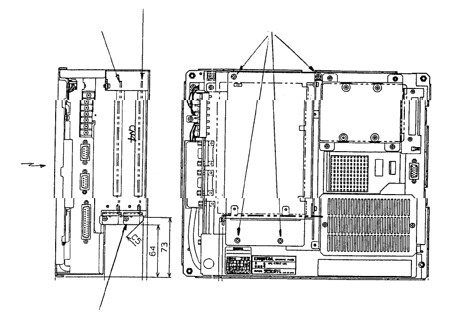
11-2 Method of Mounting ARCNET PWB
(1) Remove the 4 screws in the enlarged slot box.
(2) Disconnect enlarged slot box from main PWB (DIN connector).
(3) Attach ACRNET PWB with stop screw to connector CN4 of the removed enlarged slot box.
(4) Reconnect enlarged slot box to main PWB of main body(DIN connector).
(5) Tighten screws holding enlarged slot box to main body.
Panel computerBac
k
Position of PWB stop
screws
Front right
side
LCD
(Front)
(Bottom)
Enlarged
slot box
HDD
(Top)
Screw x 4
Mount ARCNET PWB
(E86117250A0)
Optional: Mount
A
RCNET PWB HLC
1-139