KE-750_MS.pdf - 第167页
4. 13 VC S Offset .............................................................................................................. ................. 2-52 4. 13. 1 VCS Camera Focus Offs et ..................................…
Contents
1. Application
2. Definitions
2. 1 Defining Coordinates................................................................................................................. 2-1
3. Basic Operating Procedures
3. 1 Start Up..................................................................................................................................... 2-1
3. 2 Input of Password ..................................................................................................................... 2-1
3. 3 Default Screen........................................................................................................................... 2-2
3. 4 Menu Layout.............................................................................................................................. 2-3
3. 4. 1 Menu Headings ............................................................................................................. 2-3
3. 4. 2 Display Menu................................................................................................................. 2-4
3. 5 Saving Values ........................................................................................................................... 2-8
3. 6 Common Operation................................................................................................................... 2-9
3. 6. 1 Standard Operation....................................................................................................... 2-9
3. 6. 2 Screen Scroll................................................................................................................. 2-9
3. 6. 3 Control Menu................................................................................................................. 2-11
4. Details of Operation
4. 1 Rough Adjustment of Origin...................................................................................................... 2-13
4. 2 Head Types............................................................................................................................... 2-15
4. 3 Conveyor Specifications............................................................................................................ 2-17
4. 4 Options...................................................................................................................................... 2-19
4. 4. 1 Options.......................................................................................................................... 2-19
4. 4. 2 VCS Options.................................................................................................................. 2-21
4. 5 Servo Gain ................................................................................................................................ 2-22
4. 6 Operation Specifications........................................................................................................... 2-24
4. 6. 1 Axes............................................................................................................................... 2-24
4. 6. 2 Conveyors ..................................................................................................................... 2-25
4. 6. 3 Various .......................................................................................................................... 2-27
4. 7 XY Correction Coefficients........................................................................................................ 2-28
4. 8 Comment................................................................................................................................... 2-29
4. 9 OCC .......................................................................................................................................... 2-30
4. 9. 1 OCC Offset.................................................................................................................... 2-30
4. 9. 2 Sub OCC Offset ............................................................................................................ 2-34
4. 10 CAL Block Offset ..................................................................................................................... 2-39
4. 11 Laser Offset............................................................................................................................. 2-41
4. 11. 1 Laser Offset.............................................................................................................. 2-41
4. 11. 2 Laser Scaling............................................................................................................ 2-43
4. 12 Head Offset.............................................................................................................................. 2-46
4. 12. 1 Head Offset.............................................................................................................. 2-46
4. 12. 2 Bad Mark Sensor Offset........................................................................................... 2-48
4. 12. 3 HMS Offset............................................................................................................... 2-50
2-i
4. 13 VCS Offset............................................................................................................................... 2-52
4. 13. 1 VCS Camera Focus Offset....................................................................................... 2-52
4. 13. 2 VCS Camera Scaling ............................................................................................... 2-55
4. 13. 3 VCS Camera Offset.................................................................................................. 2-57
4. 13. 4 VCS Cumulative Mounting Offset ............................................................................ 2-59
4. 13. 5 VCS Common Parameters....................................................................................... 2-62
4. 14 Coplanarity Offset.................................................................................................................... 2-64
4. 14 .1 L3 Focus Offset........................................................................................................ 2-64
4. 15 ATC Offset............................................................................................................................... 2-69
4. 16 CVS Offset............................................................................................................................... 2-72
4. 17 Standard Pick Point Position Offset......................................................................................... 2-74
4. 18 General Mounting Offset ......................................................................................................... 2-76
4. 19 Head Wait Position.................................................................................................................. 2-77
4. 20 Printing..................................................................................................................................... 2-79
4. 21 Others...................................................................................................................................... 2-80
4. 21. 1 File Input................................................................................................................... 2-80
4. 21. 2 File Open.................................................................................................................. 2-80
4. 21. 3 EEPROM Clear........................................................................................................ 2-82
4. 21. 4 VCS Version Upgrade.............................................................................................. 2-83
4. 22 Exit........................................................................................................................................... 2-85
2-ii
1. Application
This manual lays out the operating specifications for the parameters of the GX-3MS .
2. Definitions
2.1 Defining Coordinates
All parameter values and codes are defined in accordance with the system for coordinates given below.
(1) XY
Using the front of the machine as reference point, right movement is in +X coordinates,
movement towards the back is +Y.
(2) Z
Using the PWB surface as origin, upward movement is +Z.
(3) θ
When looking from above, clockwise motion is +θ
3. Basic Operating Procedures
3.1 Start Up
Select "MS Parameters" from the menu.
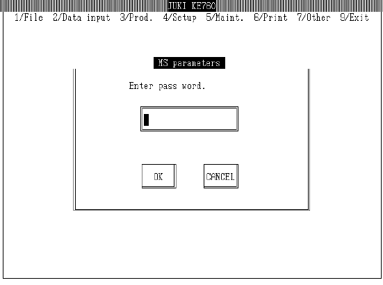
3.2 Input of Password
After selecting MS Parameters, the password is requested.
Enter password.
Once password is confirmed, MS parameter input mode is accessed.
2-1