KE-750_MS.pdf - 第190页
(1) ??? No. Item Contents 1 Z Axis (Increasing Max. Acceleration) Kp Position gain when increasing max. acceleration 2 Ki Integral value w hen increasing max. acceleration 3 Kd Differential value when increasing max. acc…
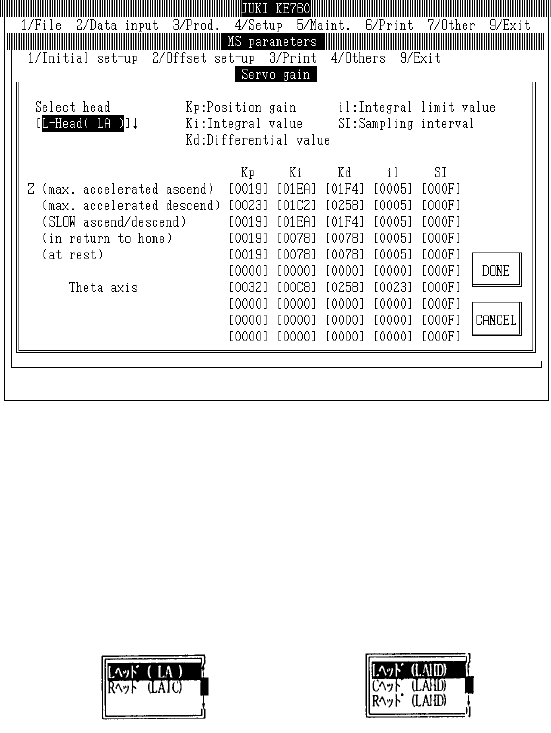
4.5 Servo Gain
Select "1/Initial set-up" then "5/Servo Gain" and the servo gain dialog will appear as follows.
Display for KE-760
LAIC head
– Setting Head
The head to be set is selected from the combination box.
Press "Alt" + " " keys and the following overview will appear.
This does not affect the "Unit Available" setting in machine setup. (Can also be selected for units
not checked "Unit Not Available".)
Setting Head [L Head (LAHD)]
[L Head (LA)]
(KE-740) or (KE-760) (KE-730) or (KE-750)
2-22

(1) ???
No. Item Contents
1 Z Axis (Increasing Max.
Acceleration) Kp
Position gain when increasing max. acceleration
2 Ki Integral value when increasing max. acceleration
3 Kd Differential value when increasing max. acceleration
4 il Integral limit value when increasing max. acceleration
5 SI Sampling interval when increasing max. acceleration
6 Z Axis (Decrease Max.
Acceleration)
Parameters when decreasing max. acceleration (Items same as Z Axis "Max.
Acceleration Increase")
7 Z Axis (Slow
Increase/Decrease)
Parameters when increasing/decreasing Z axis SLOW speed (Items same as Z
Axis "Max. Acceleration Increase")
8 Z Axis (Origin Return) Parameters for Z axis origin return, jog movements in nozzle laser height
detection, step movements (Items same as Z Axis "Max. Acceleration
Increase")
9 Z Axis (Stopping) Parameters for Z axis stopping (Items same as Z Axis "Max. Acceleration
Increase")
10 θ Axis Parameters for θ axis (Items same as Z Axis "Max. Acceleration Increase")
11 θ Axis (Encoder
Replacement)
Parameters for θ axis when LAIC head @ 2000 pulse (Items same as Z Axis
"Max. Acceleration Increase")
(2) Method of Setting
– Choose setting head with tuning button and then directly input 16 consecutive numeric values.
2-23
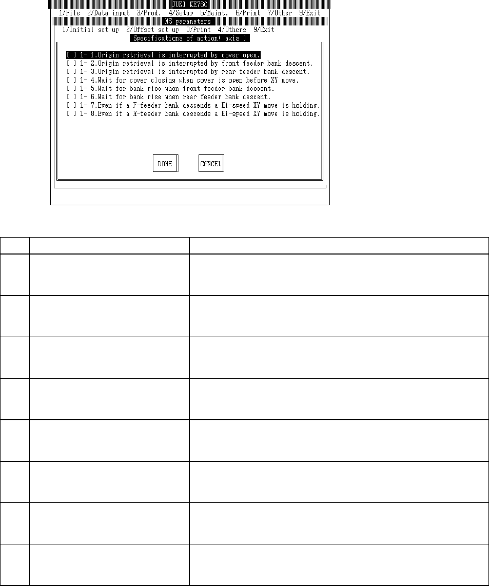
4.6 Operation Specifications
4.6.1 Axes
Select "1/Initial set-up" then "6/Specifications of action", "1/Axis" and the axis movement setting
dialog will appear as follows.
(1) Setting Items
No. Item Contents
1 1 - 1. Interruption - Cover opened during
origin return
Specifications when opened during origin return.
[ ] : Continue (Default value)
[×] : Interrupt (Origin return incomplete)
2 1 - 2. Interruption - Feeder bank (front)
lowered during home return
Specifications when front feeder bank lowers during origin return
[ ] : Continue (Default value)
[×] : Interrupt (Origin return incomplete)
3 1 - 3. Interruption - Feeder bank (rear)
lowered during home return
Specifications when rear feeder bank lowers during origin return.
[ ] : Continue (Default value)
[×] : Interrupt (Home return incomplete)
4 1 - 4. Waiting for cover to close - Cover
opened when XY axes at front.
Specifications when cover opened during XY movement.
[ ] : Disregard (Default value)
[×] : Waiting for cover to close
5 1 - 5. Waiting for bank to rise - Feeder
bank (front) lowered when XY axis at
front.
Specifications when front feeder bank descends during XY movement.
[ ] : Disregard (Default value)
[×] : Waiting for bank to rise
6 1 - 6. Waiting for bank to rise - Feeder
bank (rear) lowered when XY axis at
front.
Specifications when rear feeder bank descends during XY movement.
[ ] : Disregard (Default value)
[×] : Waiting for bank to rise
7 1 - 7. Maintain high speed XY movement
- Feeder bank (front)lowered.
Specifications for high speed XY movement with front feeder down.
[ ] : Slow down (Default value)
[×] : Do not slow down
8 1 - 8. Maintain high speed XY movement
- Feeder bank (rear)lowered.
Specifications for high speed XY movement with rear feeder down.
[ ] : Slow down (Default value)
[×] : Do not slow down
(2) Method of Setting
– Select option units listed in the above table with the check box.
2-24