KE-750_MS.pdf - 第198页
Once reference is set, select "OK" and OCC will move to X axis scaling position. Monitor image when adjustment completed With teaching adjust the monitor cross hair cursor so that it falls near the center of th…
4.9 OCC
4.9.1 OCC Offset
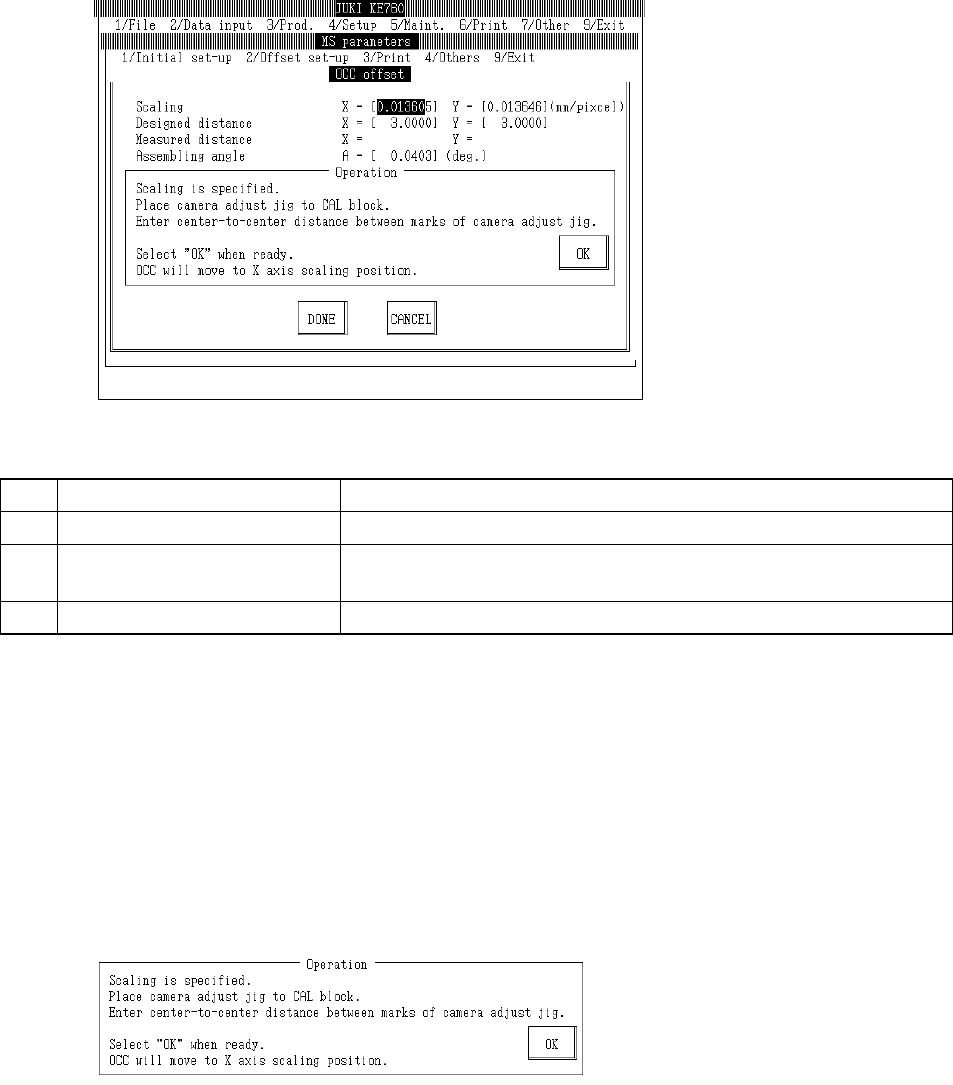
Select "2/Offset set-up" then "1/OCC", "1/OCC Offset" and the OCC offset setting dialog will appear
as follows.
(1) Setting Items
No. Item Contents
1 Scaling Size of 1 OCC pixel (mm/pixel)
2 Mark Center (Input Value) Mark pitch for scaling measurement (Spec value 3±0.001mm) (Temporary
parameter)
3 Assembling Angle Assembling angle of OCC body (in reference to main body) (° )
(2) Method of Setting
– Enter values directly from keyboard or follow operating directions to enter automatically.
– Select HOD device key to enter teaching.
– Use control menu to move head when it is in the way.
– Select "Exit" and after verification message box appears, home return will occur.
– Operating method of automatic input
Follow instructions to operate and values will automatically acquire.
c Scaling
Place camera adjustment jig onto near center of the CAL block.
Orient the camera adjustment jig under the bonding face so that the XY coordinates written on the
BOC are aligned so that the incoming direction is minus Y.
Then, place a single sheet of white paper between the camera adjustment jig and the CAL block.
Enter the marked distance of X & Y coordinates of the camera adjustment jig and CAL block. (Spec
value is 3 ア 0.001mm.)
2-30
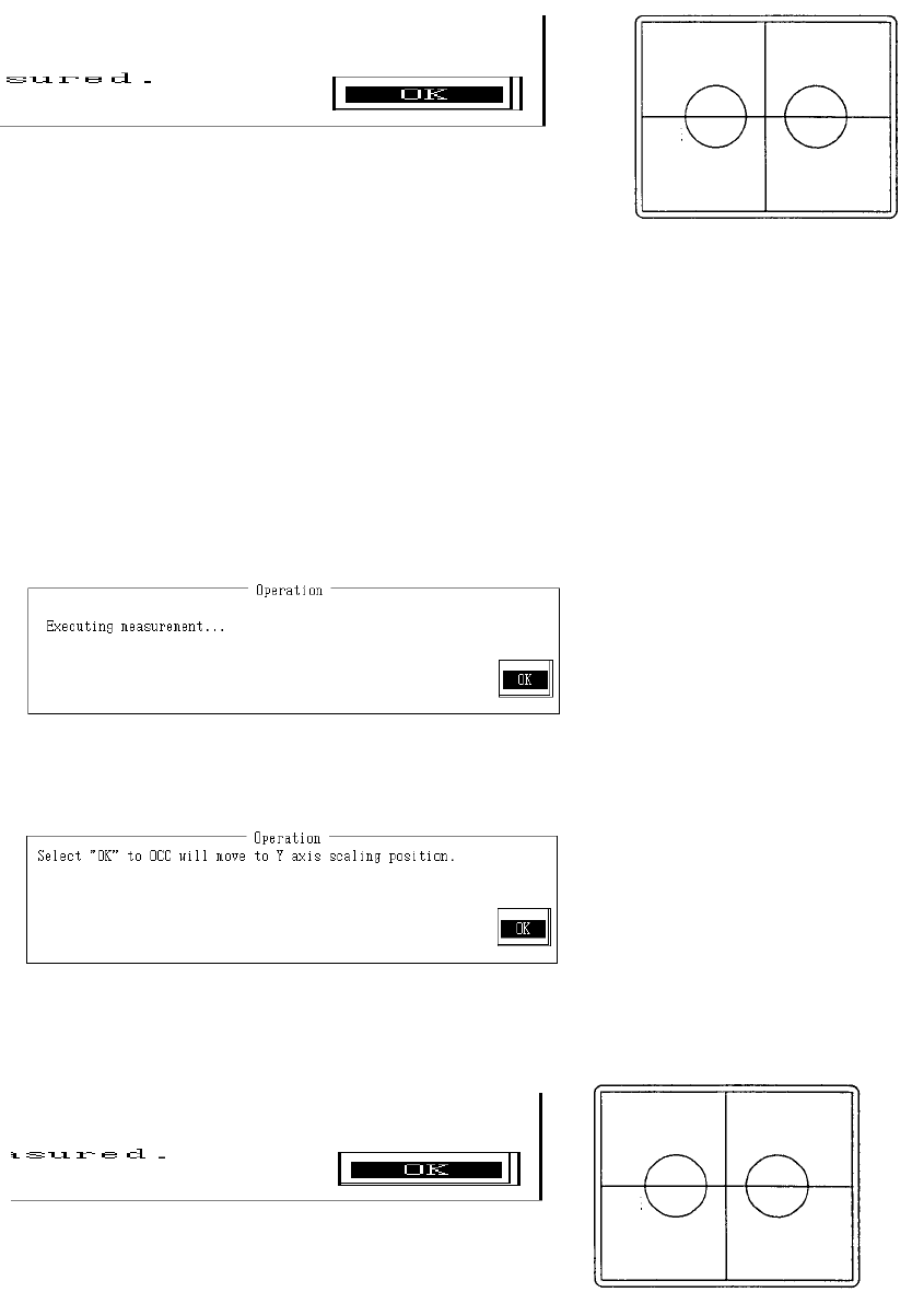
Once reference is set, select "OK" and OCC will move to X axis scaling position.
Monitor image when adjustment completed
With teaching adjust the monitor cross hair cursor so that it falls near the center of the 2 marks and
press HOD Enter key.
If no adjustment is needed, teaching is not required.
Should any dust be visible at this time, wipe the camera adjust jig thoroughly so that only the marks
are visible.
Anything visible besides the marks at time of measurement may make it impossible to take a
correct reading or may cause error.
Once the reference is determined, select "OK".
Selecting "OK" causes measurement of the distance from OCC to the X directional mark.
When measurement is completed, the measured value is displayed. From the input value and
measured value, X directional scaling is calculated and modified.
Once the reference is determined, select "OK".
Select "OK" and the OCC will move to the Y axis scaling position.
Monitor image when adjustment completed
2-31
Do the same as with the X axis and carry out adjustment of the measured position.
Once the reference is determined, select "OK".
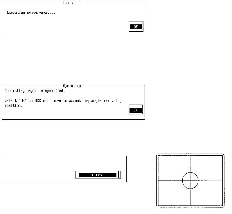
Selecting "OK" causes measurement of the distance from OCC to the Y directional mark.
When measuring is completed, the measured value is displayed. From the input value and
measured value, Y directional scaling is calculated and modified.
(2) Assembling Angle
Once the reference is determined, select "OK".
Selecting "OK" causes OCC to move to assembling angle measurement position.
Monitor image when adjustment completed
With teaching, adjust the monitor cross hair cursor so that it falls near the center of the mark and
press HOD Enter key.
Anything visible besides the marks at time of measurement will make it impossible to take a correct
reading or may cause error.
Once the reference is determined, select "OK".
Selecting "OK" causes measurement of the assembling angle.
2-32