KE-750_MS.pdf - 第21页
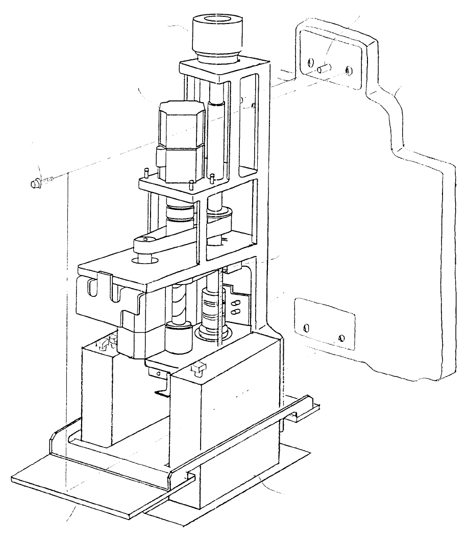
LAIC Head θ -axis encode r Positioning pin Head plate Head up SP Spring stud Diffuse r LA senso r θ -axis moto r (SL6051042TN) SEMS cap screws Z-axis moto r Fig. 2-1-3 1-15
LA Head
Head plate
Positioning pin
Head up SP
Spring stud
LA senso
r
θ-axis moto
r
(SL6051042TN)
SEMS cap screws
Z-axis moto
r
Fig. 2-1-2
1-14
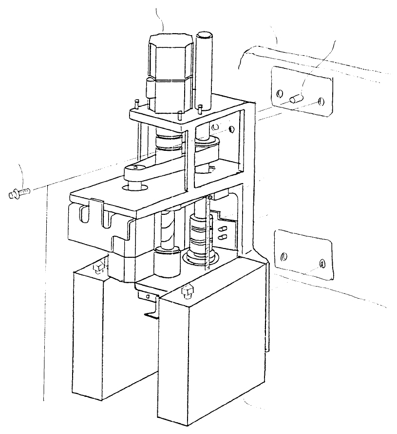
LAIC Head
θ-axis encode
r
Positioning pin
Head plate
Head up SP
Spring stud
Diffuse
r
LA senso
r
θ-axis moto
r
(SL6051042TN)
SEMS cap screws
Z-axis moto
r
Fig. 2-1-3
1-15
1-1 LAHD head
(1) Disconnect the wire bundle for Z & axes and Z-axis deceleration sensor from the head PCB and
remove the LAHD wire bundle from the connector. Disconnect air tubing from couplings.
(2) While holding head with hand so that it does not drop, remove the 4 SEMS cap screws (1).
Remove head from head plate by sliding it off positioning pins.
(Dia. 2 - 1 -1)
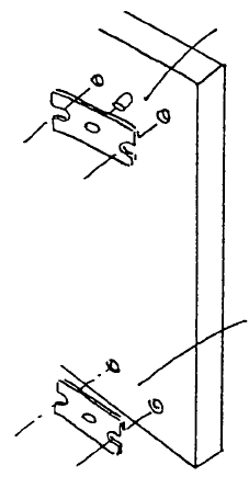
Note: There should be two shims (above & below) between the head and head plate. These shims are
used for centering the head plate and nozzle in the Y direction. When remounting head, reuse
shims. When mounting a different head, use the shims provided with it.
Stick shims to head plate with grease before mounting head.
Shim types Thickness
Head center shim A (3019721000) t0.1
Head center shim A (3020721000) t0.05
Head center shim A (3021721000) t0.03
(3) Reassemble by reversing the procedures.
Grease
Grease
Fig. 2-1-4
1-16