KE-750_MS.pdf - 第212页
– Operating method of automatic input Follow instructions to operate and values will automatically acquire. Set jig nozzle in setting head. Enter jig nozzle width and select "OK" When "OK" is selected…
(2) Purpose of these Parameter
– Due to the nature of laser sensors, corrections are required for scaling depending on the
size of the acquired parts.
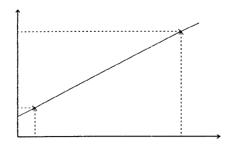
– In pixel values acquired from the laser sensor, scaling gradient (G) and coefficient (C)
display a linear correlation varying over length
P
20
P
1
SC
1
C
SC
20
Pixel values acquired
from laser
Scaling (µm/pixel)
(3) Method of Parameter Calculation
(1) Scaling of φ1 and φ20 is to be calculated
(2) From calculated scaling, scaling gradient (G) and coefficient (C) are derived.
Scaling gradient G = (SC
20
- SC1)/P
20
- P1
Scaling coefficient C = SC
20
- G x P
20
P
20
: No. of pixels acquired from laser sensor with φ20
P1 : No. of pixels acquired from laser sensor with φ1
W
20
: Actual dimensions of φ20
W1 : Actual dimensions of φ1
SC
20
: Scaling (W
20
/P
20
) for φ20
SC1 : Scaling (W1/P1) for φ1
(4) Method of conversion
– Method of converting pixel values acquired from the laser sensor over length
Length = (P x G + C) x P
P : No. of pixels acquired from laser sensor
G : Inclination of scaling
C : Coefficient of scaling
(5) Method of Setting
Head is selected with tuning button. For head selected, enter values directly with the keyboard
or follow the internal operating instructions for automatic input.
– Select HOD device key to enter teaching.
– Use control menu to move head when it is in the way.
2-44
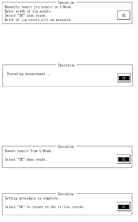
– Operating method of automatic input
Follow instructions to operate and values will automatically acquire.
Set jig nozzle in setting head.
Enter jig nozzle width and select "OK"
When "OK" is selected, the setting head jig nozzle suction is activated and setting head jig
nozzle is measured by laser.
Scaling is calculated from jig nozzle width (pixels) acquired from the laser and nozzle width
(input value).
Nozzle concentricity is the direct measured value acquired from the laser.
Measurement is taken in increments of 0° to 15° movements in the axis taking the average of 24
return movements.
When calculation is completed, the calculated result is displayed. Input width and measured
scaling nozzle concentricity are calculated and modification made.
Remove nozzle from the setting head.
Once completed, select "OK".
Setting is exited.
Select "OK" to return to default operation screen.
2-45
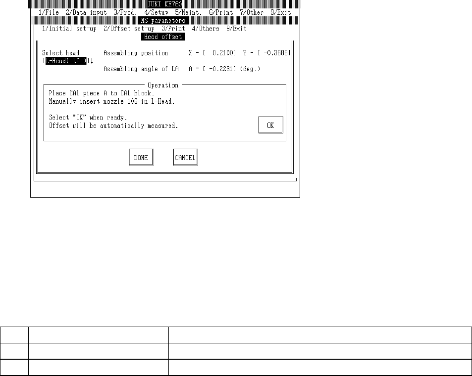
4.12 Head
4.12.1 Head Offset
Select "2/Offset set-up" then "4/Head", "1/Head Offset" and the head offset setting dialog will appear
as follows.
LA, LAHD heads : #106 Nozzle
LAIC heads : #203 Nozzle
– Setting Head
The head to be set is selected from the combination box.
Press "Alt" + " " keys and the following overview will appear.
This does not affect the "Unit Available" setting in machine setup. (Can also be selected for
units not checked "Unit Not Available".)
(1) Setting Items
No. Item Contents
1 Assembling Position Offset value for setting position of each head (OCC std)
2 Laser Assembling Angle Offset value between laser unit & main body (main body as base) ( )
(2) Method of Setting
– Head is selected with tuning button. For head selected, enter values directly with the
keyboard or follow the internal operating instructions for automatic input.
– Use control menu to move head if in the way.
– Select HOD device key to enter teaching.
– Operating method of automatic input
Follow instructions to operate and values will automatically acquire.
2-46