KE-750_MS.pdf - 第223页
When measurement is completed, the calculated re sult of X direction mark pitch is displayed. The X direction scaling value is calculated fr om input values and measurement results. Rotate VCS jig plate B 90 in or der to…
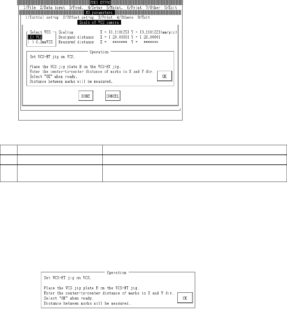
4.13.2 VCS Camera Scaling
Select "2/Offset set-up" then "5/VCS", "2/VCS Camera Scaling" and the VCS camera scaling setting
dialog will appear as follows.
(0.3 VCS only)
(1) Setting Items
No. Item Contents
1 Scaling Size of 1 VCS camera pixel (mm/pixel)
2 Mark Center (Input Value) Mark pitch for scaling measurement (Spec value 20±0.015mm)
(Temporary parameter)
(2) Method of Setting
– Select VCS unit with the tuning button of the setting unit and enter values directly with the
keyboard or follow the internal operating instructions for automatic input.
– Select HOD device key to enter teaching.
– Use control menu to move head if in the way.
– Operating method of automatic input
Follow instructions to operate and values will automatically acquire.
(0.3 VCS only)
Set VCS-HT jig in standard VCS.
When setting 0.3mm VCS, set a 0.3mm adaptor in VCS-HT jig.
Set VCS jig plate B in VCS-HT jig so measurement can be taken in the X direction.
Enter mark pitch of jig in X & Y directions. (Spec value 20 ア 0.015mm.)
Once completed, select "OK".
When "OK" is selected, X direction mark pitch is measured by VCS.
2-55
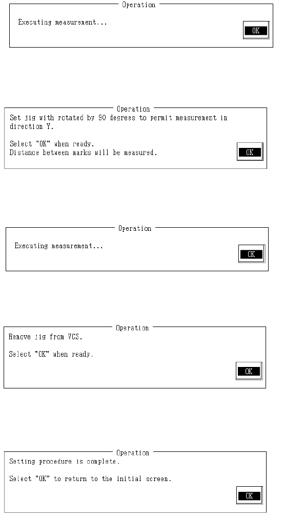
When measurement is completed, the calculated result of X direction mark pitch is displayed.
The X direction scaling value is calculated from input values and measurement results.
Rotate VCS jig plate B 90 in order to measure in Y direction.
Once completed, select "OK".
When "OK" is selected, Y direction mark pitch is measured with VCS.
When measurement is completed, the result of Y direction mark pitch measurement appears. Y
direction scaling is calculated from input values and measurement result and modification made.
Remove VCS plate B from VCS-HT jig.
Remove 0.3mm adaptor from VCS-HT jig when setting 0.3mm VCS.
Remove VCS-HT jig from VCS and select "OK".
Setting is completed.
Select "OK" to return to default operation screen.
2-56
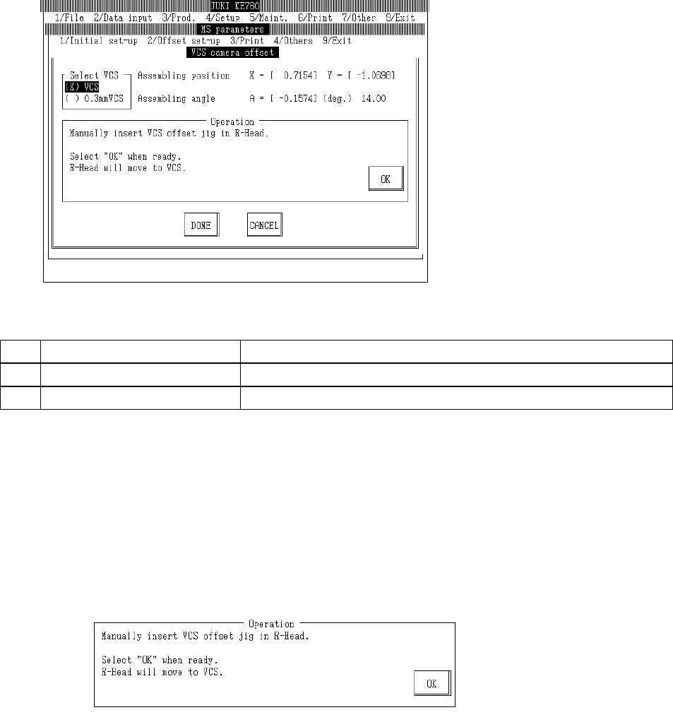
4.13.3 VCS Camera Offset
Select "2/Offset set-up" then "5/VCS", "3/VCS Camera Offset" and the VCS camera offset setting
dialog will appear as follows.
(1) Setting Items
No. Item Contents
1 Assembling position Offset value from VCS camera setting position
2 Assembling angle Assembling angle of camera (in reference to main body) (° )
(2) Method of Setting
– Select VCS unit with the tuning button and enter values directly with the keyboard or follow
the internal operating instructions for automatic input.
– Select HOD device key to enter teaching.
– Use control menu to move head if in the way.
– Operating method of automatic input
Follow instructions to operate and values will automatically acquire.
Set VCS-HT jig in LAIC head.
Once completed, select "OK".
When "OK" is selected, AIC head moves to recognition position.
2-57