KE-750_MS.pdf - 第226页
4.13.4 VCS Mounting General Offset Select "2/Offset set-up" then "5/VCS", "7/Place ment offset of VCS" and the VCS mounting general offset setting dialog will appear as follows. (1) Setting …
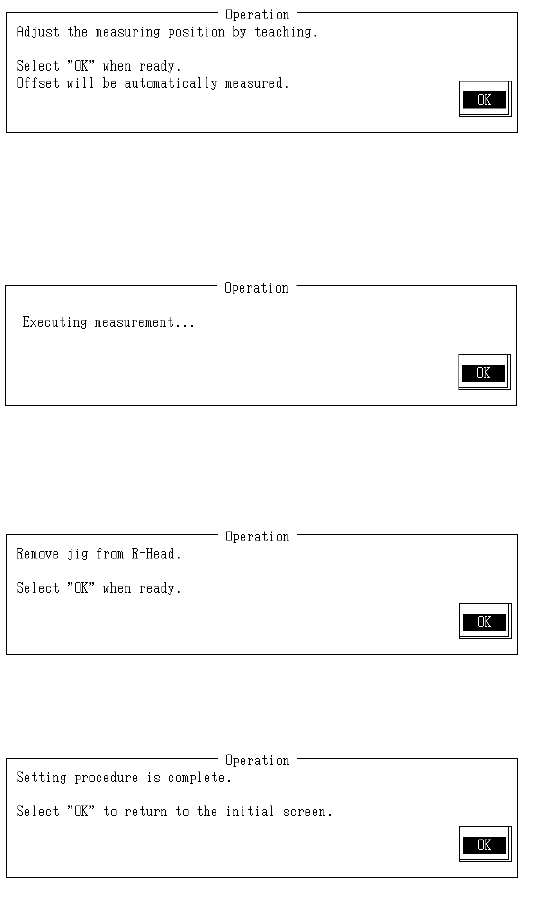
Adjust monitor cross cursor with teaching so that mark is nearly centered and press HOD Enter
key.
Once completed, select "OK".
Selecting "OK" measures offset.
When measurement is completed, assembling angle and assembling position are calculated
from the measurement result and modifications made.
From the obtained offset, move mark to VCS center.
Remove VCS offset jig from LAIC head.
Once completed, select "OK".
Setting is completed.
Select "OK" to return to default operation screen.
2-58
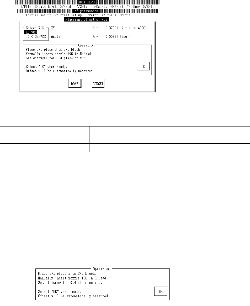
4.13.4 VCS Mounting General Offset
Select "2/Offset set-up" then "5/VCS", "7/Placement offset of VCS" and the VCS mounting general
offset setting dialog will appear as follows.
(1) Setting Items
No. Item Contents
1 XY VCS XY general offset value of mounting component
2 Angle VCS angle general offset value of mounting component (° )
(2) Method of Setting
– Select VCS with the tuning button and enter values directly with the keyboard or follow the
internal operating instructions for automatic input.
– Select HOD device key to enter teaching.
– Use control menu to move head if in the way.
– Accessory functions
F7 key: Verifies that current VCS mounting general offset is 0 .
F8 key: Verifies that current VCS mounting general offset is 180 .
– Operating method of automatic input
Follow instructions to operate and values will automatically acquire.
(Standard VCS)
2-59
(0.3mm VCS)
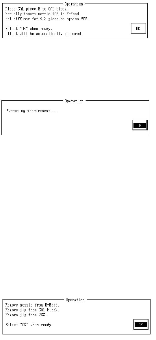
Set CAL piece B onto CAL block.
Set #106 nozzle in LAIC head.
Set a 0.4 glass diffuser in VCS for a standard VCS. For 0.3mm VCS use a 0.3 glass diffuser.
Once completed, select "OK".
When "OK" is selected, offset is measured.
– Content of Measurements
(1) Turn on CAL block vacuum to initialize suction.
(2) Once OCC recognizes the position of the piece, central position and gradient are
calculated. If both of the holes in the piece are not recognized, error will occur.
If error occurs, verify piece position.
(3) LAIC head takes piece with suction and CAL block vacuum shuts off. At this time the
gradient of the piece calculated in (2) is corrected.
(4) Piece moves to setting VCS recognition position.
(5) Setting VCS recognizes piece and calculates its center position offset and gradient.
(6) Mount piece in center of CAL block and turn vacuum on to hold it. At this time, offset of
center position and gradient of piece calculated in (5) are corrected.
(7) OCC recognizes position of piece and calculates central position and gradient.
(8) XY mounting general offset is calculated from the piece center calculated in (7) and CAL
block center and modifications are made.
(9) Mounting general offset assembling angle is calculated from piece gradient calculated in
(7) and modifications are made.
If the recognized center of gravity between the monitor cross cursor and mark is skewed when
mounting position of piece is recognized in (7), repeat automatic measurement.
Remove #106 nozzle from LAIC head.
Remove CAL piece B from CAL block.
Remove diffuser from VCS.
When completed, select "OK".
2-60