KE-750_MS.pdf - 第231页
4.14 Coplanarity Offset 4.14.1 L3 Focus Offset Select "2/Offset set-up" then "6/Coplanarity", "1/Foc us Offset of L3" and the L3 focus offset dialog will appear as follows. (1) Setting Items…
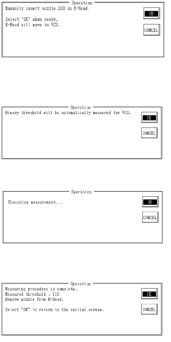
– Operating method of automatic input
Follow instructions to operate and values will automatically acquire.
Set #203 nozzle in LAIC head.
Once completed, select "OK".
When "OK" is selected, nozzle moves to setting VCS.
– Contents of Measurement
(1) The binary threshold value is automatically measured with nozzle.
Once measurement is completed, result is displayed.
Remove #203 nozzle from LAIC head.
Once completed, select "OK" or "Cancel".
When "OK" is selected, the binary threshold values of setting VCS are modified and operating
screen clears.
When "Cancel" is selected, the binary threshold values of setting VCS are not modified and
operating screen clears.
2-63
4.14 Coplanarity Offset
4.14.1 L3 Focus Offset
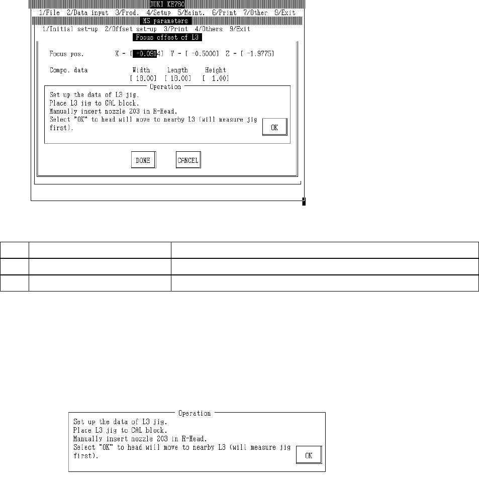
Select "2/Offset set-up" then "6/Coplanarity", "1/Focus Offset of L3" and the L3 focus offset dialog
will appear as follows.
(1) Setting Items
No. Item Contents
1 Focus Position Offset value from L3 sensor focus set position
2 Parts Data L3 jig parts data for focus offset measurement (temporary parameter)
(2) Method of Setting
– Enter values directly with the keyboard or follow the internal operating instructions for
automatic input.
– Select HOD device key to enter teaching.
– Operating method of automatic input
Follow instructions to operate and values will automatically acquire.
Input L3 jig data.
Place L3 jig on top of CAL block.
When jig suction is turned on, OCC recognizes L3 jig position. L3 jig is placed onto CAL block so
that its 2 holes see the CAL block illumination.
Manually set #203 nozzle in LAIC head.
When "OK" is selected, LAIC head suction takes L3 jig and laser recognizes L3 jig.
When recognition of L3 jig is completed, head moves to a spot nearby (parking point). Displace
of L3 is automatically corrected based on the recognition result.
2-64
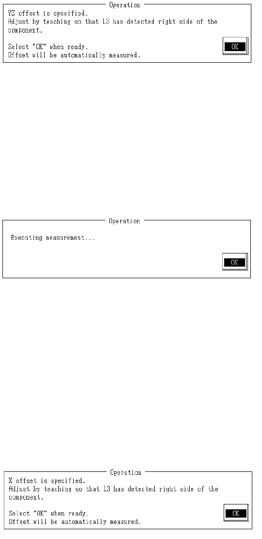
(1) Y, Z Offset
With teaching adjust piece so L3 is to the right where position can be detected and press HOD
Enter key.
When there is no piece in L3 focus, the red LED lights.
When L3 jig is positioned so L3 can detect, red LED extinguishes.
Adjust L3 jig position to just where the red LED of the L3 extinguishes.
A measured position once reached with teaching is valid as long as setting dialog is open.
To carry out subsequent measurement without teaching, select "Enter".
Once completed, select "OK".
When "OK" is selected, L3 is scanned in the Y direction and offset in Y & Z directions is
measured.
When L3 jig measurement is completed, the Y & Z offset of the focus position is calculated from
the measurement results and modification made.
– Contents of Measurement
(1) To secure the foreflow section, the L3 jig measures in +Y direction after moving in -Y
direction.
(2) L3 jig measures in -Y direction.
(3) From the measurement results in (1) & (2), correction of focus position is made and (1) &
(2) are remeasured.
(4) From the measured results, Y & Z offset for the focus position are calculated and
modified.
(2) X Offset
With teaching adjust piece so L3 is to the right where position can be detected and press HOD
Enter key.
Since offset correction has already been made for Y & Z offset measurement in the Y direction
position, only adjust the X direction.
When there is no piece in L3 focus, the red LED lights.
When L3 jig is positioned so L3 can detect, red LED extinguishes.
Adjust L3 jig position to just where the red LED of the L3 extinguishes.
A measured position once reached with teaching is valid as long as setting dialog is open.
To carry out subsequent measurement without teaching, select "Enter".
2-65