KE-750_MS.pdf - 第233页
Once completed, select "OK". When "OK" is selected, L3 is scanned in the X dire ction and offset in that direction is measured. When L3 jig measurement is completed, the X offs et of the focus positio…
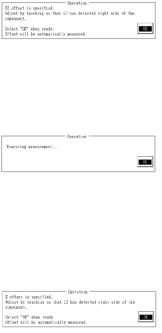
(1) Y, Z Offset
With teaching adjust piece so L3 is to the right where position can be detected and press HOD
Enter key.
When there is no piece in L3 focus, the red LED lights.
When L3 jig is positioned so L3 can detect, red LED extinguishes.
Adjust L3 jig position to just where the red LED of the L3 extinguishes.
A measured position once reached with teaching is valid as long as setting dialog is open.
To carry out subsequent measurement without teaching, select "Enter".
Once completed, select "OK".
When "OK" is selected, L3 is scanned in the Y direction and offset in Y & Z directions is
measured.
When L3 jig measurement is completed, the Y & Z offset of the focus position is calculated from
the measurement results and modification made.
– Contents of Measurement
(1) To secure the foreflow section, the L3 jig measures in +Y direction after moving in -Y
direction.
(2) L3 jig measures in -Y direction.
(3) From the measurement results in (1) & (2), correction of focus position is made and (1) &
(2) are remeasured.
(4) From the measured results, Y & Z offset for the focus position are calculated and
modified.
(2) X Offset
With teaching adjust piece so L3 is to the right where position can be detected and press HOD
Enter key.
Since offset correction has already been made for Y & Z offset measurement in the Y direction
position, only adjust the X direction.
When there is no piece in L3 focus, the red LED lights.
When L3 jig is positioned so L3 can detect, red LED extinguishes.
Adjust L3 jig position to just where the red LED of the L3 extinguishes.
A measured position once reached with teaching is valid as long as setting dialog is open.
To carry out subsequent measurement without teaching, select "Enter".
2-65
Once completed, select "OK".
When "OK" is selected, L3 is scanned in the X direction and offset in that direction is measured.
When L3 jig measurement is completed, the X offset of the focus position is calculated from the
measurement results and modification made.
– Contents of Measurement
(1) Measurement is taken in the X direction while the L3 jig is being displaced.
(2) From the measured results, X offset for the focus position are calculated and modified.
– Carry out measurement 5 times or more to improve accuracy of the focus position Z
parameter. Do not use teaching from the second time on.
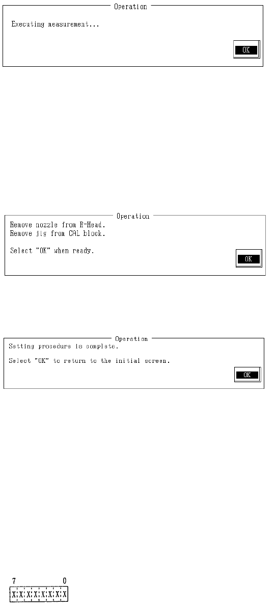
Remove #203 nozzle from LAIC head.
Remove L3 jig from CAL block .
When completed, select "OK".
Setting is completed.
Selecting "OK" returns to default operating menu.
(3) Details of L3 Status
When L3 makes a mistake in part recognition, "Error" is displayed.
Message
"E004054 L3 has made a recognition error.
Status: ?? Error code: ??"
Status (8 byte)
2-66

Status Report (When byte on)
Byte Content
7 Small interpolation loss from single lead
6 Initializing (L3 internal initialization)
5 Calculating
4 Acquiring
3 Data available
2 Status error
1 Sensor initializing
0 Stand-by (can receive commands)
Example:
Stand-by
Status: 01 Error code: XX
Data available & stand-by
Status: 09 Error code: XX
Error: Insufficient data
Status: 05 Error code: 02
2-67