KE-750_MS.pdf - 第28页
2. Z Slider Shaft (IC) Assy Replacement When replacing Z slider shaft (IC) assy, MS parameters related to Z-axis height and the laser must be reentered. (Refer to secti on 2 - 13 for data reentry.) (1) Remove air tube (1…
After replacing head, center nozzle & head. Part of the MS parameters will have to be reentered.
(Refer to section 2 - 13.)
– Centering nozzle (X direction)
When assembling, the LAIC head is used as basis for vertical alignment with the base surface.
The LA centered with reference to the LAIC head. Thus, when the LA head is replaced, the LAIC
head serves as reference for centering.
For method of adjustment, refer to the QA Table under Head, Head centering (X direction).
– Centering nozzle (Y direction)
In the Y direction, the distance is determined by shims between head & head plate.
For method of adjustment, refer to QA list under Head, Head centering (Y direction).
1-21
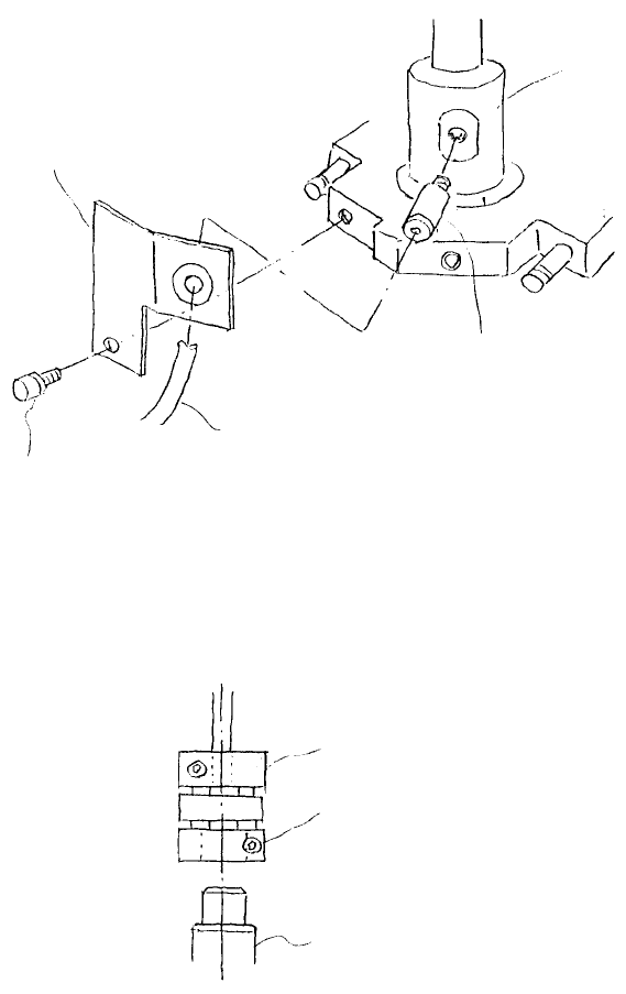
2. Z Slider Shaft (IC) Assy Replacement
When replacing Z slider shaft (IC) assy, MS parameters related to Z-axis height and the laser must be
reentered. (Refer to section 2 - 13 for data reentry.)
(1) Remove air tube (1) from half union (2) and remove SEMS cap (3). Remove rotation stopper (4).
Remove half union from rotary stopper.
(2) Loosen fastening screw of coupling and separate coupling from Z slide shaft.
Rotary bloc
k
Half union (hex type)
A
ir tube
SEMS cap scre
w
(SL6030642TN)
Rotation stoppe
r
Fig. 2-2-1
Fastening scre
w
Z slider shaft
Coupling
Fig. 2-2-2
1-22
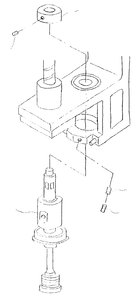
(3) Loosen the 2 screws (2) holding set collar (1) and lift collar to remove. Loosen screw (3) and lower Z
slider shaft (IC) assy to remove.
Note: Before removing Z slider shaft (IC) assy, first remove LAIC head defuser.
Rubber pushe
r
Stop scre
w
(SM8040602TP)
Z slider shaft (IC)
assy
Stop scre
w
(part of set collar)
Set colla
r
Fig. 2-2-3
1-23