KE-750_MS.pdf - 第30页
(4) Reassemble in reverse sequence. Be sure to check the following points. – Z slider shaft Z direction (Refer to QA list Head, Z slider shaft Z direction.) – Z slider shaft XY direction (Refer to QA list Head, Z slider …
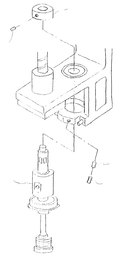
(3) Loosen the 2 screws (2) holding set collar (1) and lift collar to remove. Loosen screw (3) and lower Z
slider shaft (IC) assy to remove.
Note: Before removing Z slider shaft (IC) assy, first remove LAIC head defuser.
Rubber pushe
r
Stop scre
w
(SM8040602TP)
Z slider shaft (IC)
assy
Stop scre
w
(part of set collar)
Set colla
r
Fig. 2-2-3
1-23
(4) Reassemble in reverse sequence. Be sure to check the following points.
– Z slider shaft Z direction
(Refer to QA list Head, Z slider shaft Z direction.)
– Z slider shaft XY direction
(Refer to QA list Head, Z slider shaft XY direction.)
– External layout of diffuser & nozzle
(Refer to QA Table, Head, Diffuser fastening position.)
1-24
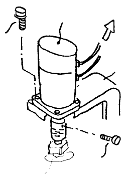
3. Z-axis Motor Replacement
After replacing Z-axis motor, Z-axis home positioning must be adjusted and height and laser related MS
data must be reentered. (Refer to section 2 - 13 for reentry.)
Head bracket
Head motor PCB
Z-axis moto
r
SEMS cap
screw
(1)
Ball scre
w
Fig. 2-3-1
(1) Disconnect Z-axis wire bundle from head motor PCB. Loosen screw (1), remove the 4 SEMS caps
(2) and remove Z-axis motor.
(2) When mounting, align Z-axis motor shaft axis with ball screw axis. (Refer to QA Table, Head, Z
motor axis alignment.)
(3) After replacement, adjust Z-axis home positioning and tighten coupling screw (1). (Refer to QA
Table, Head, Z-axis home adjustment.)
1-25