KE-750_MS.pdf - 第58页
Chapter 4 OCC Unit 1. OCC Unit Replacement 1-1 Main OCC Unit (1) Remove SEMS cap screws (1), (2) and remove camera bracket D. (2) Camera unit assy is held by the 4 SEMS cap scr ews (3) and light unit assy is held by the …

9. Summary of Readjustments Required after Replacement
Bad mark sensor HMS Head main PWB Blow S/V
Sensor height
{
Bad mark sensor offset
{
HMS height
{
HMS offset
{
Head vacuum level
{
Speed controller
{
1-50
Chapter 4 OCC Unit
1. OCC Unit Replacement
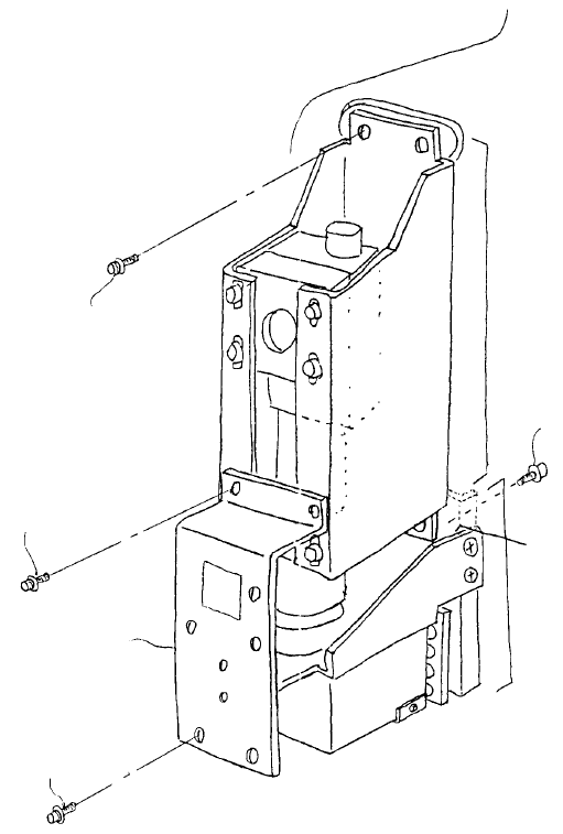
1-1 Main OCC Unit
(1) Remove SEMS cap screws (1), (2) and remove camera bracket D.
(2) Camera unit assy is held by the 4 SEMS cap screws (3) and light unit assy is held by the 2 SEMS
cap screws (4). Remove connectors before removing and replacing both assemblies.
(3) Reassemble in reverse sequence.
(4) After replacing camera unit assy, adjust focus and enter MS parameters. After replacing light unit
assy, adjust polarizing filter and OCC light. (Refer to 4 - 7 Summary of Readjustments Required
after Replacement.)
Camera bracket D
E3809725000
Left light unit ass
y
E38117250A0
SEMS cap screw x 2
SL6041092TN
SEMS cap screw x 2
SL6030692TN
SEMS cap screw x 4
SL6041092TN
SEMS cap screw x 2
SL6030892TN
Camera unit ass
y
E38017250A0
Head plate
Fig. 4-1-1
1-51
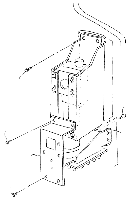
1-2 Sub OCC Unit
(1) Remove SEMS cap screws (1), (2) and remove camera bracket D.
(2) Camera unit assy is held by the 4 SEMS cap screws (3) and light unit assy is held by the 2 SEMS
cap screws (4). Remove connectors before removing and replacing both assemblies.
(3) Reassemble in reverse sequence.
(4) After replacing camera unit assy, adjust focus and enter MS parameters. After replacing light unit
assy, adjust polarizing filter and OCC light. (Refer to 4 - 7 Summary of Readjustments Required
after Replacement.)
Camera bracket D
E3809725000
Left light unit ass
y
E38117250A0
SEMS cap screw x 2
SL6041092TN
SEMS cap screw x 2
SL6030692TN
SEMS cap screw x 4
SL6041092TN
SEMS cap screw x 2
SL6030892TN
Camera unit ass
y
E38017250A0
Head plate
Fig. 4-1-2
1-52